


NOTE: DIAGRAMS & ILLUSTRATIONS NOT TO SCALE.
12
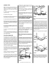
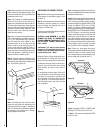
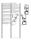
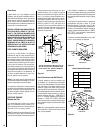
The offset and return elbows may be attached
together, or a section or sections of chimney
may be used between, but do not exceed 20' in
total length between elbows. If sections of pipe
exceed 10' between elbows, a chimney stabi-
lizer must be used at the midpoint (
Figure 35
).
The stabilizer support straps must be attached
under tension (in shear) to structural framing
members above. When two sets of elbows are
used, the maximum combined length of chim-
ney used between elbows cannot exceed 20'
(
Figure 36
). Example: If C
1
= 10' then C
2
cannot
exceed 10'.
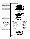
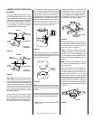
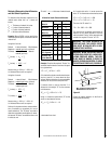
If an offset exceeds 6' in length, each chimney
joint beyond the first 6' of offset to the return
elbow, must be secured by a No. 8 x ¹⁄₂" sheet
metal screw located at the underside of the joint
(
Figure 37
).
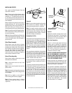
A ¹⁄₈" diameter hole must be drilled in the
chimney joint using a ¹⁄₈" diameter drill. Hole
should be drilled in center of joint overlap
(
Figure 38
). Be sure to drill only through the
outer chimney casting. Do not puncture the
inner flue.
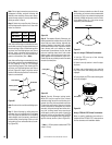
Maximum offset of chimney system is 30°.
Two offsets must not be assembled to form a
60° offset. However, two sets of offset and
return elbows may be used on a single flue
system, provided the total height of the sys-
tem exceeds 25'.
Return elbow support straps must be se-
curely attached under tension (in shear) to
structural framing members above. Do not
substitute a FTF8/10-30 offset elbow in place
of a FTF8/10-E30 return elbow.
Figure 36
Figure 35
Stabilizer
A
1
20'
Max.
B
1
10' Max.
Offset
Elbow
Return
Elbow
A
1
C
1
B
1
B
2
C
2
A
2
A
1
C
1
B
1
B
2
C
2
A
2
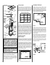
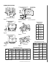
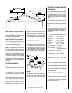
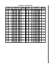
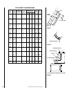
OFFSET CALCULATIONS
Step 1. Use Offset Chart to determine amount
of horizontal offset (A) and height (B) for vari-
ous chimney section assemblies.
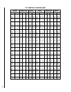
Step 2. Use “Height of Chimney Only” column
in The Vertical Elevation Chart to determine
combinations of chimney used above return
elbow to achieve desired heights. Reference
Components Effective Height Chart in vertical
elevation chart section.
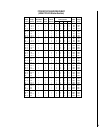
Step 3. Use Elevation Chart as job estimator
only. Add necessary firestop spacers and stabi-
lizers as required. Firestop spacers must be
used as shown in
Figures 22 and 23
and stabi-
lizers as shown in
Figure 27
.