


6
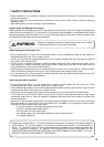
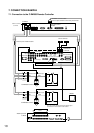
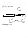
[Rear Panel]
5 6
7
8
9
10
11
ALARM/ / REMOTE IN
CAMERA SELECT OUT ALARM / REMOTE OUT
MASTER / SLAVE
RS-232C
OFF
ON
TERMINATION
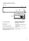
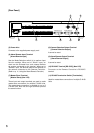
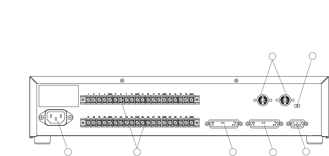
(5) Power Inlet
Connects to the supplied power supply cord.
(6) Alarm/Remote Input Terminal
[Alarm/Remote Input]
Use the Mode Selection switch (4) to perform input
function settings. When set to "Alarm" input, an
alarm can be activated from such external devices
as sensors connected to this terminal. When set to
"Remote" input, this terminal permits the selection of
the camera connected to the Remote Controller.
(Refer to p. 11; Using the Alarm/Remote Function.)
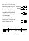
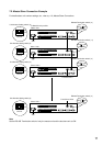
(7) Master/Slave Terminal
[Master/Slave] (Non LPS)
These input and output terminals are used to make
master/slave connections for multiple C-AL80 Units.
The master/slave connection is possible for up to 8
C-AL80 units. Both left and right terminals provide
the same function.
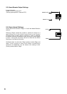
(8) Camera Selection Output Terminal
[Camera Selection Output]
It cannot be used.
(9) Alarm/Remote Output Terminal
[Alarm/Remote Output]
It cannot be used.
(10) RS-232C Terminal [RS-232C] (Non LPS)
Connects to the Remote Controller's RS-232C
terminal.
(11) RS-485 Termination Switch [Termination]
Used for master/slave connection of multiple C-AL80
Units.