


Form RZ-NA I-UDA, P/N 195673 Rev 5, Page 18
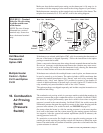
18. Flame
Rollout
Switch -
Sizes 30-125
only
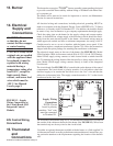
16. Combustion
Air Proving
Switch
(cont’d)
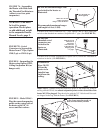
Sizes 30-125 are equipped with a temperature activated manually reset flame rollout
switch. The flame rollout switch is located at the top of the burner assembly. It is
factory set and is non-adjustable. If the setpoint is reached, the flame rollout acts to
interrupt the electric supply to the gas valve. If the flame rollout switch activates,
identify and correct the cause before resetting the switch. Refer to the Mainte-
nance Section for information on probable causes and instructions on resetting the
flame rollout switch. (For location, see FIGURE 18, page 31.)
DANGER: If the manual reset flame rollout switch activates,
identify and correct the cause before resetting the switch. Never
bypass the flame rollout switch; hazardous conditions could result.
See Hazard Intensity Levels, page 2.
17. Limit Control
All units are equipped with a temperature activated auto reset limit control. The
control is factory set and is non-adjustable. If the setpoint is reached, the limit
control will interrupt the electric supply to the gas valve. This safety device pro-
vides protection in the case of motor failure or lack of airflow due to a restriction at
the inlet or outlet. (For location, see FIGURE 18, page 31.)
CAUTION: The auto reset limit control will continue to shut down
the heater until the cause is corrected. Never bypass the limit
control; hazardous conditions could result. See Hazard Intensity
Levels, page 2.
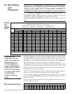
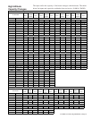
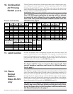
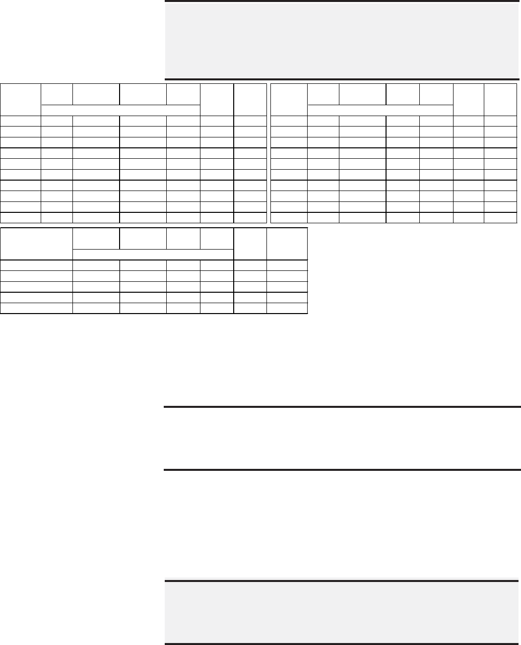
The two Tables on the left below list the approximate water column negative pres-
sure readings and switch setpoints for sea level operating conditions for Model
UDAP and Model UDAP-CV heaters. The Table on the right lists the approximate
water column differential pressure readings and switch setpoints for sea level op-
erating conditions for Model UDAS heaters.
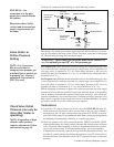
Pressure Switch Settings
DANGER: Safe operation of this unit requires proper venting
flow. NEVER bypass combustion air proving switch or attempt
to operate the unit without the venter running and the proper
flow in the vent system. Hazardous conditions could result. See
Hazard Levels, page 2.
Startup Equilibrium Setpoint Setpoint Startup Equilibrium Setpoint Setpoint
Cold Hot OFF ON Cold Hot OFF ON
30 1.00 0.78 0.40 0.58 Green 197030 30 1.00 0.78 0.65 0.83 Yellow 197028
45 0.95 0.75 0.40 0.58 Green 197030 45 1.05 0.80 0.65 0.83 Yellow 197028
60 1.00 0.78 0.50 0.68 Orange 196388 60 1.10 0.85 0.65 0.83 Yellow 197028
75 1.00 0.85 0.50 0.68 Orange 196388 75 1.10 0.85 0.65 0.83 Yellow 197028
100 0.85 0.72 0.50 0.68 Orange 196388 100 0.85 0.72 0.55 0.73 White 196362
125 0.75 0.60 0.40 0.58 Green 197030 125 0.75 0.60 0.45 0.63 Pink 197032
150, 175 0.75 0.65 0.40 0.58 Green 197030 150, 175 0.75 0.60 0.40 0.58 Green 197030
200, 225 2.20 1.50 1.10 1.30 Blue 201158 200, 225 2.20 1.50 1.10 1.30 Blue 201158
250, 300 2.30 1.60 1.10 1.30 Blue 201158 250, 300 2.30 1.60 1.10 1.30 Blue 201158
350, 400 2.60 1.80 1.40 1.60 Red 201159 350, 400 2.60 1.80 1.40 1.60 Red 201159
Startup Equilibrium Setpoint Setpoint
Cold Hot OFF ON
1.10 0.84 0.65 0.83 Yellow
1.10 0.81 0.50 0.68 Orange
0.92 0.75 0.60 0.78 Lt Blue
0.97 0.78 0.60 0.78 Lt Blue
0.88 0.71 0.55 0.73 White100
Switch
P/N
197028
196388
197029
197029
196362
30
45
60
75
Differential Pressure Measured in " w.c.
Model
UDAS
Label
Color
Switch
P/N
Negative Pressure Measured in " w.c.
Label
Color
Switch
P/N
Model
UDAP
Label
Color
Negative Pressure Measured in " w.c.
Model UDAP-CV
with Opt AV6