


20
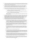
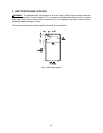
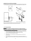
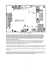
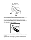
MOUNTING THE 2-STAGE RIELLO BURNER:
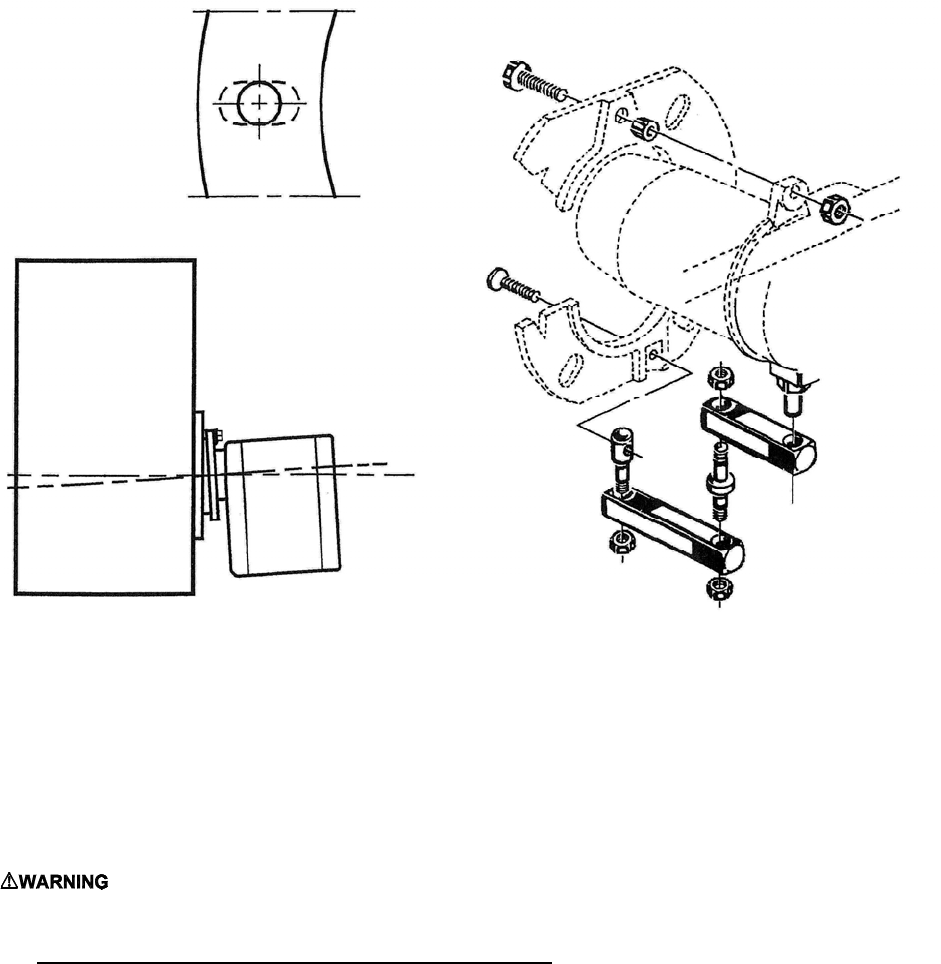
It is necessary that the insulation gasket be placed between the mounting plate and the burner flange.
The insulating gasket has six holes, which, if necessary, can be modified as shown. (see figure 14-1)
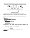
Figure 14-1: Burner gasket and mounting Figure 14-2: Burner fixing and hinge assembly
Verify that the installed burner is lightly leaned towards the button. (See figure 14-1) The burner is
designed to allow entry of the flexible oil-lines on either side of the burner.
I. OIL TANK AND PIPING:
: All local codes and ordinances take precedence with regard to selection and
installation of oil storage tank and oil supply (and return) lines. In the absence of local codes, all
tanks and lines must be selected and installed according to the instructions in this manual and
the Standard for the Installation of Oil-Burning Equipment
, NFPA 31-1997, or the latest edition.
1. The use of black steel pipe and malleable iron fittings is recommended for all fuel oil service
lines. Never use galvanized steel piping or fittings for any fuel oil lines.
2. Where practical, provide rigid supports for the piping.
3. If the piping size in a run must be reduced, use reducing couplings only. Avoid the use of
reducing bushings.
4. Remove all pipe thread burrs and inspect the pipe for dirt or other foreign material prior to
connecting. If present, remove any deposits in the piping and discard any excessively corroded
piping.