


10
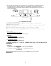
NOTE: On the OL6 it is possible to rotate the flue elbow (which is factory installed for vertical discharge)
90°
counter clockwise from the vertical position to adapt to various venting systems.
Notice:
Blocked Vent Switch Installation
The blocked vent switch kit must be installed to comply with CAN STD B140.4 where applicable. For
installation instructions see AOPS2687 kit.
c CAUTION MUST BE TAKEN NOT TO EXCEED 90° ROTATION (OF THE FLUE
ELBOW) .
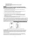
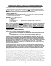
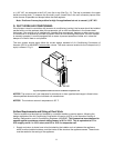
ROTATION OF FRONT FLUE ELBOW:
When an installation requires that the flue exit out the left side casing, remove screw securing the 90
deg. elbow and rotate it 90°. Then, remove knock-out in side casing and extend vent through the opening.
A trim collar may be ordered from Thermo Products to hide the gap around the flue pipe. This trim collar,
however, is not required for operation. Trim collar/gasket part numbers(s) 14121 / 330073 for OL6.
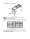
The OL6 may be vented through a standard correctly sized chimney.
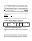
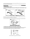
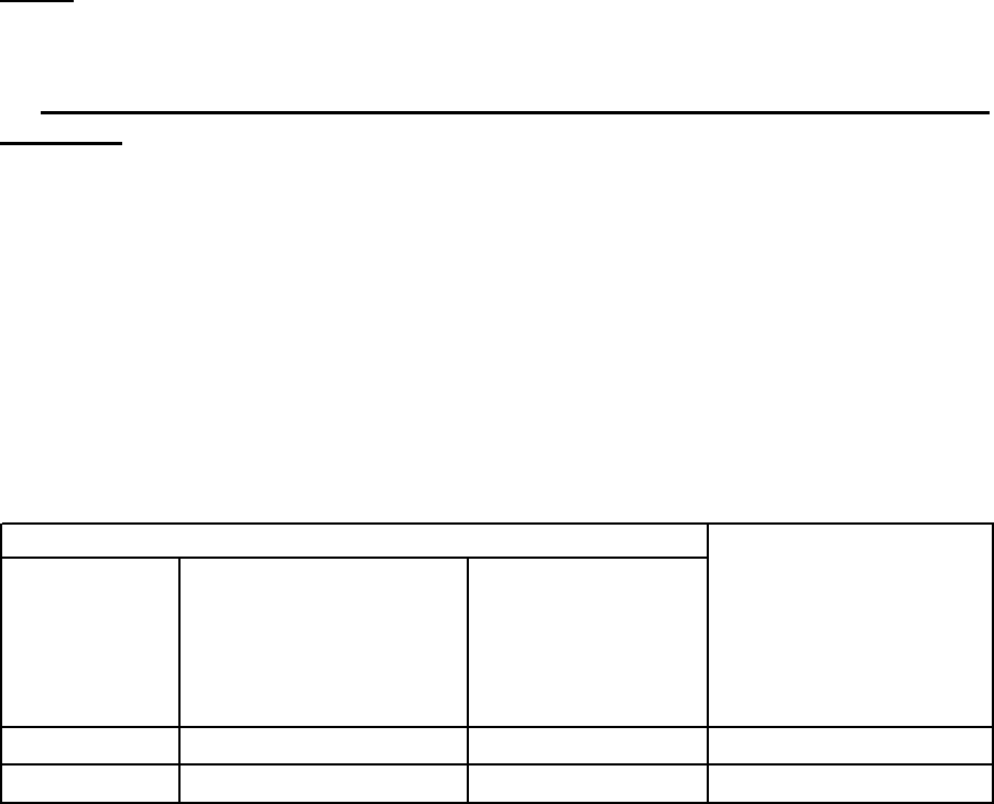
The OL6 may also be horizontally vented through a sidewall. Thermo Products has available the Field
model FDVS-45/FOVP-415 side wall vent kit for such applications. When installing the sidewall vent kit,
outside combustion air must also be applied to the burner. The following table identifies application order
information.
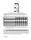
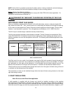
Table 2: Sidewall vent kits
The Field vent kit is set up with 4 inch diameter vent pipe for OL6 with concentric through-the-wall vent
termination/inlet air vent hood. The combustion air inlet pipe diameter is also 4 inch diameter. For Riello,
the combustion air inlet pipe will be reduced to 3 inch diameter with the Riello sidewall vent kit. For
Beckett, the combustion air inlet pipe will be reduced to 3” diameter with the Beckett sidewall vent kit.
The side wall vent may be installed either through the knock-out on the right or left side casing of the unit
or vertically out the top opening of the vestibule.
The combustion air inlet can be installed through either the lower left side casing knockout or the lower
right side casing knockout.
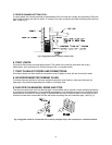
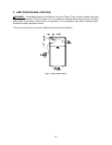
C. DRAFT REGULATORS:
Note: Do not use with Direct Vent application.
A draft regulator is supplied with the furnace and should be installed according to the regulator
manufacturers recommendations. With the burner operating, use a draft gauge to adjust the regulator to
the proper setting. (refer to the instructions enclosed with draft regulator to adjust to the proper setting).
When the burner air supply and draft are properly adjusted, the over fire draft should be a negative (-).01"
FIELD VENT TERMINATION
KIT
SIDE WALL VENT
A
CCESSORIES KIT
COMBUSTION AIR INTAKE
HOOD KIT
(15’ application MAX) (BURNER SPECIFIC)
(FOR COMBUSTION AIR
A
PPLICATIONS ONLY
)
THERMO PRODUCTS PART
NUMBER
THERMO PRODUCTS
PART NUMBER
THERMO PRODUCTS PART
NUMBER
(OL6)
Beckett AFG AOPS8393 AOPS8394 AOPS8397
Riello BF3 AOPS8393 AOPS8395 AOPS8416
BURNER
SIDE WALL VENTING APPLICATION ORDER INFORMATION