


59
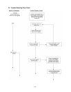
2. Make sure thermostat is calling for burner operation.
3. Check oil supply and make sure all valves are open.
A. DIAGNOSTICS:
To assist in troubleshooting this appliance, it is equipped with an integrated safety and ignition control
with diagnostics. These diagnostics include an indicator light that relays the operational status of the
control and can help in diagnosing the condition of the flame sensor.
Diagnostic Features:
The Honeywell brand model R7184B (or alternate R7184U) safety and ignition control module used on
this unit continuously monitors the operation of the heating system. If an abnormal condition occurs, the
LED light on the control will rapidly flash indicating the operational status of the unit. In event this control
malfunctions, the entire control should be replaced. It is not field-repairable.
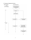
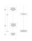
In the event of an operational failure of the burner system, the rate of flashes, if any, of the ignition control
module LED should be noted, before turning off power to the unit. Otherwise, power to the heating
section will be interrupted and the control LED will not furnish the diagnostic flashing. It may be necessary
to restart the furnace and have the failure occur again. For the model R7184B, under normal operating
conditions, the LED will be continuously lit while the burner is operating.
If either control has sensed a flame failure, which was uncorrected by initiating another trial-for-ignition,
the control will cease ignition trials and shutdown the burner, or “lockout”. The LED will continuously flash
at a high rate (approximately 1/2-second “on”; 1/2 second “off”, for the model R7184B.
: If the appliance fails to relight after resetting the primary control twice contact a qualified
service company. DO NOT continue to reset primary control.
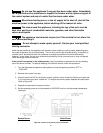
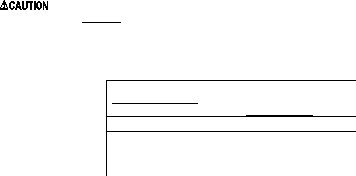
The operational condition of the flame sensor, or “cad cell”, can be checked by depressing the reset
button on the control module, while the burner is operating. Count the number of flashes of the LED and
compare them to the table below.
Number of flashes
Cad Cell Resistance (in ohms)
Model R7184B
1
0 to 400
2
400 to 800
3
800 to 1600
4
1600 ≤
If it is necessary to troubleshoot the flame sensor independently of the burner primary, the following
procedure may be used.
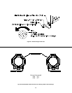
B. CAD CELL CHECKOUT PROCEDURE:
1. Stop burner and shutoff electrical power to the appliance.
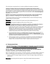
2. Open burner junction box (on top of the burner blower) and remove the plug-in portion of the cad cell
by pulling it forward from and clear of the receptacle. Connect an ohmmeter across cad cell pins. With the
cell exposed to direct room light, the measured resistance should be less than 2500 ohms (in fact, it may
be less than 200 ohms).