


All installations and services must be performed by qualified service personnel.
4
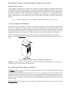
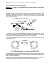
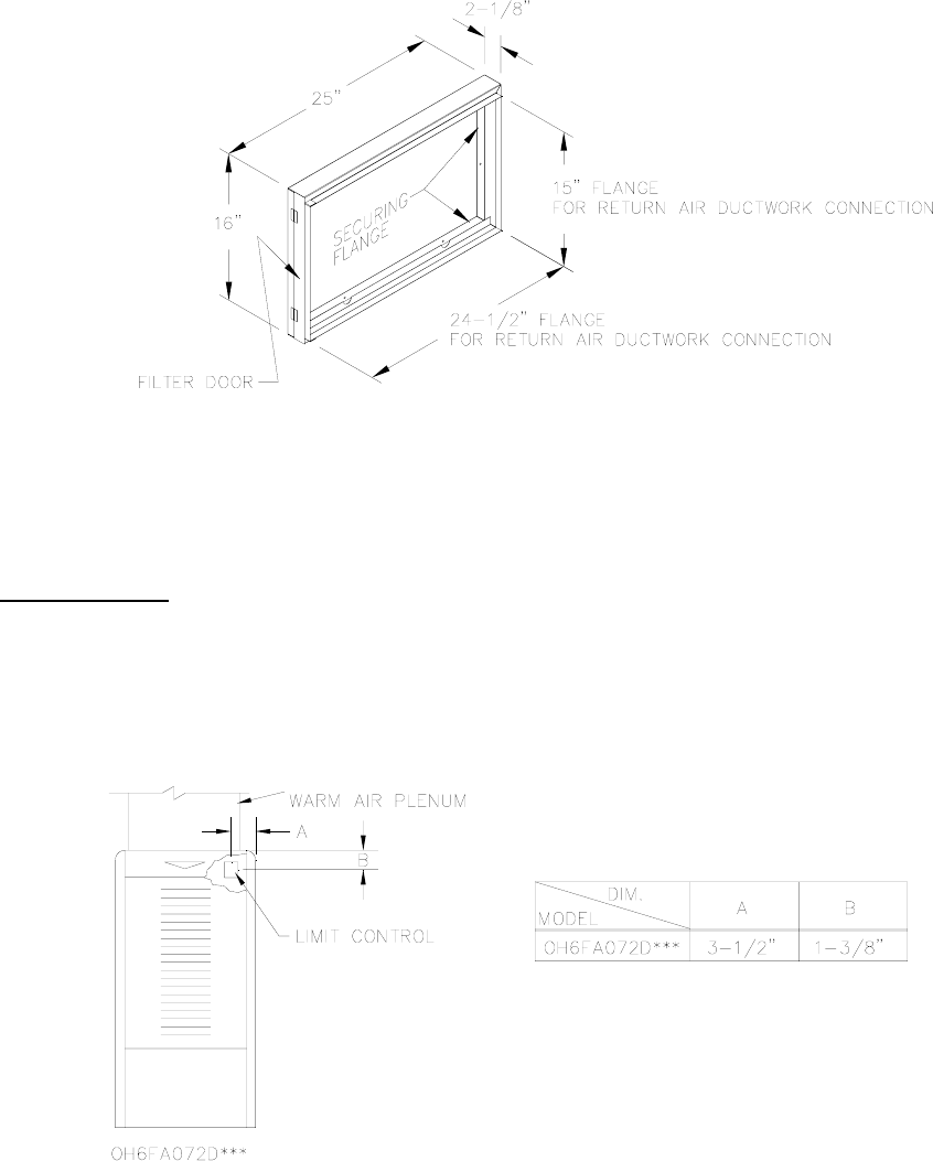
Position the open end of the filter rack so as to provide access for filter replacement. Once the filter rack is
positioned correctly, scribe a line along the inside of the securing flange on three of the sides. To scribe a line on the
fourth side (the open end), use the open end support as a guide.
Remove the filter rack and cut the return air opening in the casing. Now the filter rack can be anchored to the
furnace with screws or pop-rivets through the securing flange of the filter rack.
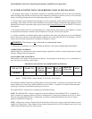
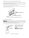
Connect the return air plenum to the filter rack and slide the filter into place. Dimensions for adapting the return air
plenum to the filter rack are provided (See Fig. 5).
Fig. 5: A typical filter rack and dimensions for the OH6FA072D*** furnace.
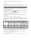
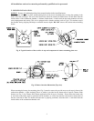
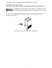
E. LIMIT POSITION AND LOCATION
cWARNING: The predetermined limit locations on all of the Thermo Pride oil fired furnaces
have been tested and approved by Thermo Products, LLC. Any attempt to relocate these safety
controls or replace these safety controls with a control that is not approved, or is incompatible,
may result in personal injury, substantial property damage or death.
The unit listed in the table below must have the fan and limit control installed at the time of unit installation.
Fig. 7: Limit location for OH6FA072D***
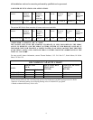
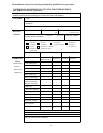
TABLE 2: Installation location of
the fan and limit control for each
furnace