


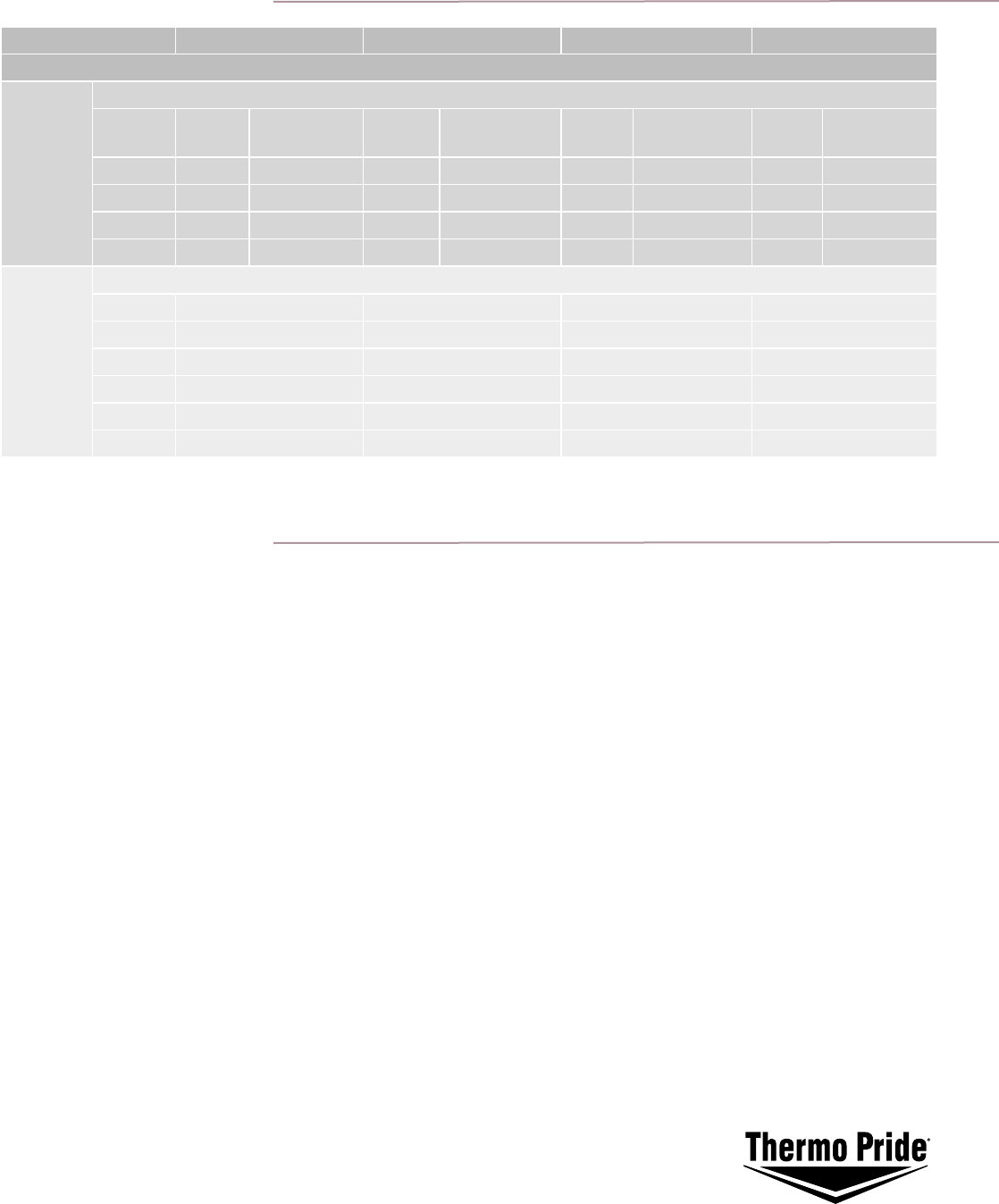
ECM Specifications
Model Number * OL5-85...E OL11-105...E OH5-85...E OH11-105...E
CFM from .1 - .6” W/C
Cooling
(100 cfm
steps
available
for A/C)
A/C Tonnage Selection
A/C
CFMs
Continuous
Fan
A/C
CFMs
Continuous
Fan
A/C
CFMs
Continuous
Fan
A/C
CFMs
Continuous
Fan
2 ton 800 500 800 500 800 500 800 500
2.5 ton 1000 500 1000 500 1000 500 1000 500
3 ton 1200 600 1200 600 1200 600 1200 600
3.5 ton 1400 700 1400 700 1400 700 1400 700
Heating
(at approx.
rated input
BTU)
Air Temperature Rise Selection
Heating CFM Heating CFM Heating CFM Heating CFM
57° Rise 1400 — 1400 —
63° Rise 1260 1500 1260 1500
69° Rise 1162 1350 1162 1350
75° Rise 1050 1245 1050 1245
83° Rise 938 1125 938 1125
The standard motor size may not support this cfm at high static pressures.
* Model numbers end with ‘E’ to signify ECM motor.
General
• Eliminates the need for air temp thermostat to control fan cycling by using time instead.
• Selectable blower turn-on and turn-off delays to adjust comfort & efficiency
(turn-on: 30, 60, 120 & 240 sec; turn off: 2, 4, 6 & 8 min)
• ree blower operating choices: HEAT, COOL & FAN for best efficiency for each mode.
• Reduces A/C blower speed 50% on demand to increase dehumidification.
• Cooling blower delays of 10 seconds on, and 45 seconds off to enhance cooling comfort and efficiency.
Cycle Control
• 4 minute minimum A/C off time to reduce Short-Cycle related failures.
• A high limit will cause the blower run at the selected HEAT speed. It will then run for the HEAT turn off
time afterwards in the absence of a HEAT call.
• Blower operation will “time out” before mode is switched between HEAT & COOL to prevent stress related
evaporator failures.
• Burner Cut-Off on high limit
Speed Control
• Selectable air temperature (heat) rise from Return to Supply Plenum (choose from: 63, 69, 75 and 85
º
F)
• Selectable CFM rates for matching A/C tonnages. ese CFM selections support from 2.0 to 3.5 tons.
• Maximum CFM’s are limited by the maximum RPM of the ECM motor and the duct static pressure.
Please refer to the manual addendum for guidelines.
Diagnostics
• Control Input LED’s indicate active thermostat input lines.
• Diagnostic LED indicate:
1. Active Operation (turn full on during burner or compressor operation)
2. A HIGH LIMIT condition. (flash on/off at 2 ½ times per second)
Additional Features
Form No. PL81410021002 - 6/05 - 20Ms
Printed in the U.S.A.
© 2005 ermo Pride - North Judson, IN
Phone: 574-896-2133
www.thermopride.com