


All installations and services must be performed by qualified service personnel.
6
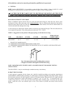
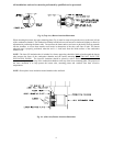
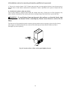
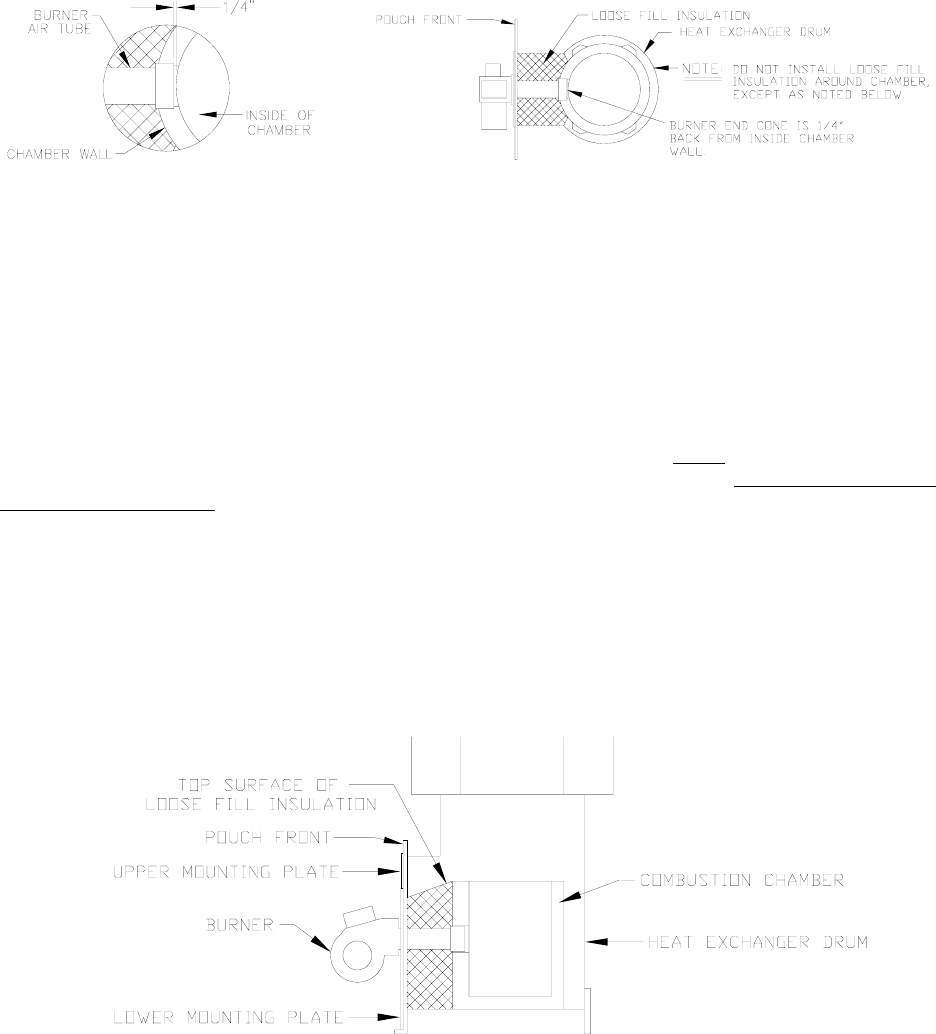
Fig. 9: (Top view) Burner insertion illustration
When mounting the burner, the upper mounting plate (Fig. 8) must be removed to provide access to the area in front
of the combustion chamber. The combustion chamber can then be moved forward or backward slightly to allow for
adjustment in positioning the burner tube. Do not allow the burner tube or end cone to physically touch or protrude
into the chamber, as excess heat transfer could result in destruction of the tube, end cone or both. The burner
tube/end cone is properly positioned, when the end is ¼ inch back from the inside surface of the combustion
chamber wall.
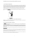
NOTE: The loose-fill insulation that is included in a brown paper bag should be lightly
placed around the burner
tube between the front of the combustion chamber and the burner mounting plate. (DO NOT PACK THE
INSULATION DOWN). The loose-fill insulation should be placed in such a fashion that the surface of the
insulation is sloped from the top of the combustion chamber to the top of the lower mounting plate. The purpose of
the loose insulation is to help protect the burner tube, mounting plates and vestibule area from excessive
temperatures.
NOTE: Do not place loose insulation around chamber sides and back .
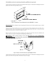
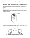
Fig. 10: (Side view) Burner insertion illustration