


26
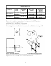
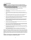
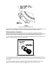
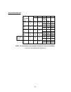
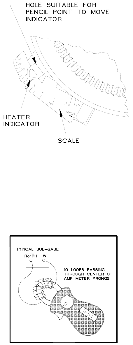
Figure 16: Heat Anticipator Adjustment Scale
In many cases, this setting can be found in the thermostat installation instructions. If this information is not
available, or if the correct setting is questioned, the following procedures should be followed:
Preferred method of adjustment:
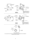
Using an analog ammeter on the lowest scale, such as an Amp Check, connect the meter across
terminals “R” and “W” on the sub-base (“RH” & “W” on an isolating thermostat sub-base). If the reading is
too low to move the needle on to the measurement scale of the instrument, proceed as follows:
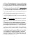
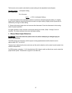
1. Wrap 10 loops of single strand, insulated, thermostat wire around the prongs of an ammeter, refer to
Figure 17. Set the scale to the 1 to 5 or 1 to 6 amp. scale.
Figure 17: Analog Ammeter w/ Wire Loops to Boost Reading
2. Connect the bare ends of this wire jumper across terminals “R” and “W” on the sub-base (“RH” and
“W” on an isolating thermostat sub-base). This test must be performed without the thermostat attached to
the sub-base.
3. Let the heating system operate in this position for about one minute. Read the amp meter scale.
Regardless of the value of the meter reading, divide the value by 10 (for 10 loops of wire).