


34
Humidifier
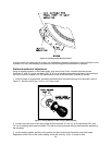
The control provides a 120 VAC output for a humidifier. Connections are made to a male quick
connect terminal labeled “FAN”. The control does not switch this output, it provides a pass-through
connection from P1-7 from the switched primary voltage of the Burner Module.
Status LED
A red LED is provided to indicate any thermostat input has been recognized by the microprocessor on
the control. See Diagnostic Features for a function description of operation.
Thermostat Input LEDs
Four green LEDs are placed beneath their respective thermostat connections (W, Y, G and DEHUM)
and operate whenever a call is present. See Diagnostic Features for a function description of
operation.
C. Operating Modes
Standby Mode
All outputs are off and the control is waiting for a thermostat demand. The thermostat inputs, and limit
switch are continuously monitored. The control initiates action when a thermostat call is received or
limit switch opens.
Fan Mode
A call for fan (“G”) is received from the thermostat. If no other mode is calling for blower operation, the
control will operate the fan relay (K4) and power the “Low” blower speed terminal. The fan mode will
be operated as long as the “G” input is calling and neither the Heat mode nor the Cool mode is calling
for blower operation. When the Heat and Cool modes call for blower operation, their respective
outputs will take precedence after their respective turn-on time delays have expired.
Cooling Mode
A call for cool (“Y”) is received from the thermostat. If the heat mode is not active or the anti-short
cycle delay is not in effect, the control will energize the “CC” terminal and after a 10 second power
demand conservation delay energizes the “COOL” speed blower terminal.
When the call for cool is satisfied, the “CC” terminal is de-energized and the cooling off delay of 45
seconds is started. Forty-five seconds later the “COOL” speed blower terminal is de-energized and
the control reverts to Standby Mode.
Dehumidification Operation
If a call for dehumidification is received while the Cool Mode is active, blower speeds will be reduced.
The PSC “COOL” blower speed terminal (1158-100 model only) will be de-energized and “Low” blower
speed will be energized.
Anti-Short Cycle Operation
To prevent compressor short cycling, a call for cooling will be ignored for four minutes after the
termination of any cooling call. The anti-short cycle delay is also in effect at power-up.
Heat Mode
When a call for heat (“W”) is received from the thermostat, if the “Cool” mode is not already active, the
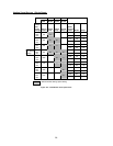
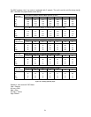
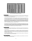
“T-T” terminal is energized and the blower on delay is started. The on-off pattern of DIP switch SW2
(positions 1 and 2) select one of four blower on delay values (see Table 11). When the delay time has
elapsed, the “HEAT” blower speed is energized. The control remains in steady heat mode until the
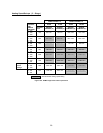
thermostat is satisfied. When the call for heat signal is removed, the “T-T” terminal is de-energized and
the blower off delay is started. The on-off pattern of DIP switch SW2 (positions 3 and 4) select one of
four blower off delay values (see Table 11). When the delay time has elapsed, the “HEAT” blower
speed terminal is de-energized.