


57
If it is necessary to troubleshoot the flame sensor independently of the burner primary, the following
procedure may be used.
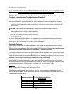
B. CAD CELL CHECKOUT PROCEDURE:
1. Stop burner and shutoff electrical power to the appliance.
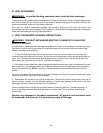
2. Open burner junction box (on top of the burner blower) and remove the plug-in portion of the cad cell
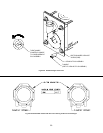
by pulling it forward from and clear of the receptacle. Connect an ohmmeter across cad cell pins. With the
cell exposed to direct room light, the measured resistance should be less than 2500 ohms (in fact, it may
be less than 200 ohms).
3. Check the resistance across the cad cell pins with the cell covered (protected from exposure to
ambient light). The resistance should be greater than 20,000 ohms.
4. If cell resistances are different from above, replace the plug-in portion of cell, (Honeywell Part No.
130367).
5. Carefully reinsert the plug-in portion of the cad cell into the receptacle. If the cad cell appears to be
functioning correctly, troubleshoot the fan control module and the safety and ignition control (primary
control) module, according to the Honeywell instructions covering the devices.
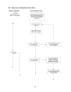
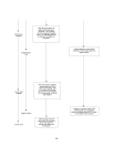
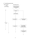
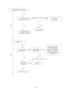
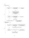
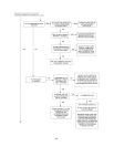
The troubleshooting chart beginning on the following page should help identify the type of malfunction or
deviation from normal operation. To use this diagram, just follow the instructions in the boxes. If the
answer is yes or the condition is true, go down to the next box. If the answer is no or the condition is
false, go to the box on the right. Continue checking and answering questions and conditions in each box
until a problem and/or repair is found. After any maintenance or repair, the trouble shooting sequence
should be repeated until normal system operation is achieved.