


All installations and services must be performed by qualified service personnel.
33
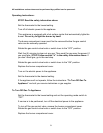
3. The following formula may be used to calculate the heat input rate for the
appliance:
Gas heating value x Amount of gas consumed = Heat input rate, or
Amount of time required to consume the gas
BTU/cu ft x Number of cu ft x 3600 seconds = Input rate (BTU/hr).
Seconds for one revolution x 1 hour
In cases where a gas meter is not installed on the fuel gas supply line, the input
rate can be assumed to be approximately correct if the burner manifold pressure
is the same as that shown on the rating label.
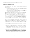
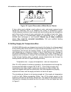
Make sure the gas supply pressure at the appliance falls within the allowable
range for the type of fuel gas. See table 8. The pressure to the furnace must be
checked while the burner, and any other gas appliances, on the same supply
system are operating. Measure the pressure using a pressure gauge, or
manometer, at the 1/8 in. NPT plugged tap on the inlet side of the appliance gas
control valve, shown in the General Gas Piping Requirements section of this
manual. An Allen wrench is normally required to remove the plug from the valve.
Make sure the fuel gas is shut off before removing this plug and installing a
pressure test gage.
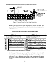
Table 8: Allowable Gas Pressures for All MHA1/MDA1 Models
Type of
Fuel Gas
Range of
Supply
Pressure
(in. W.G.)
Manifold
Pressure
(in. W.G.)
Natural 14.0 - 4.5 3.5 (± .3)
Propane 14.0 - 11.0 10.0 (±. 3)
This appliance is equipped with multiple, identical, fixed, main burner orifices
sized for the fuel gas and manifold pressure shown on the rating label. The input
rate can only be increased, or decreased, by adjusting the manifold pressure.
To adjust the manifold gas pressure to the main burners:
a. With the gas shutoff, remove the 1/8 in. NPT threaded pipe plug located
on the front side of the main burner gas manifold. Use a U-tube
manometer or pressure gage, capable of measuring pressure in inches of
water column, to measure the gas pressure at this point.