


All installations and services must be performed by qualified service personnel.
9
G. Duct Work and Air Conditioning
Design and installation of the duct system should follow the current guidelines of
the Air Conditioning Contractors of America (ACCA) or the American Society of
Heating, Refrigeration and Air Conditioning Engineers, Inc. (ASHRAE).
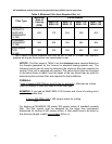
All furnaces are tested over a range of external static pressure that simulates the
airflow resistance of the ductwork, fittings, and diffusers connected to the furnace
for a typical (average) duct system. The furnace blower and blower motor have
been selected to work successfully against the following range of duct system
resistance.
Recommended range of duct system resistance for all models: 0.2 to 0.5 in.
W.G. external static pressure.
When the furnace is installed in a small room, and no return air ducts are used,
the return openings to the unit should extend full size to a location outside the
furnace room.
If the furnace is used in connection with summer air conditioning (cooling), the air
conditioner’s evaporator coil must be installed on the air outlet side of the
furnace to avoid water vapor condensation in the furnace heat exchanger.
NOTICE: Return air grilles and supply registers in the air distribution system
should not be obstructed.
H. Filters/ Filter Installation
Filters must be installed external to the furnace casing.
It is necessary to cut the return air opening in one or both side(s) of the MHA1
models depending upon the needs of the specific installation.
This MHA furnace has been factory supplied with a high quality re-usable filter
rated for air velocities up to 600 ft/min. An optional Thermo Products filter rack
assembly (part no. AOPS7547 for MHA50, 75, 100 and AOPS7375 for the
MHA125) is available which, is sized for the filter provided.
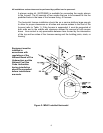
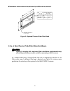
If an optional Thermo Pride filter rack (Figure 3) is used with the furnace, square knock
outs have been provided on each side casing to act as a template for the cut out.
Scribe lines connecting the outside corners of each knockout, cut side casing along
lines. Position the open end of the filter rack so that it is accessible for filter
replacement. Attach the filter rack to the furnace with screws or pop-rivets along the
securing flange. Connect the return plenum to the filter rack and slide the filter into
place.