


2
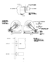
15. The L37 and L39 blower must be assembled (the L33 blower is pre-assembled) and then installed into unit.
(See Fig. 3 for L33 or Fig. 4 & 5 for L37 and L39). Assemble legs to blower with (4) 5/16-18 X 5/8 hex head self
tapping machine screws, (4 per side).
16. The motor (3/4 HP for L37 or 1HP for L-39) must be mounted to the motor mounting plate then mounted to the
mounting plate support angles on the furnace base, (Refer to Fig. 4).
Notice: The motor provided is a dual voltage 230/115V motor. Ensure motor is wired for your application.
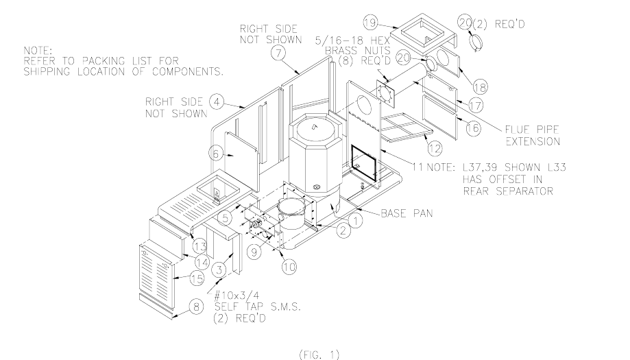
17. Install filter rack (12) into clips on rear side casings and rear separator making certain rack engages all clips on
separator and side casings. (See Fig. 1).
18. Install one trim ring with gasket (20) over flue on inside of top rear panel then install top rear panel (18) with the
other trim ring (20) on outside of the top rear panel. (See Fig.1)
19. Set rear bottom panel (16), access door (17), top rear panel (18) and top rear section (19) in place. Align factory
drilled holes and metal screw panels in place. Assemble door handles on door. Make certain door can be readily
removed and replaced. (See Fig. 1).
20. Install top front section (13) and top front panel (14) then fasten with hex head sheet metal screws.
(See Fig. 1).
21. Assemble door handles on door and install front access door (15). Make certain door can be readily removed and
replaced. (See Fig. 1).
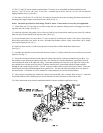
22. Fasten the external wire harness to the right side casing of the furnace in the pre punched holes provided. Use
the machine screws and nuts provided to fasten the 4 X 4 junction box with the attached 60" greenfield (for fan &
limit switch) to the front of the right side casing. Fasten the remaining box to the rear of the right side casing in the
pre punched holes with the screws provided. Fasten the shortest piece of greenfield with the straight connector
through the side casing into the rear box. The 90
°
connector is then used to connect to the blower motor. Fasten the
remaining mid sized greenfield through the front junction box. The free end of this greenfield piece is to attach to
the burner motor. Consult the oil service manual for wiring schematics to wire the external harness.
23. After properly positioning the chamber for burner insertion depth, (face of burner head recessed ¼ inch back
from inside chamber wall) carefully place loose fill insulation in front of chamber to above burner tube.
24. Follow instructions in the furnace installation manual for burner installation and burner set-up.