


All installations and services must be performed by qualified service personnel.
36
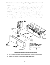
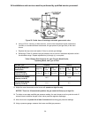
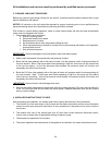
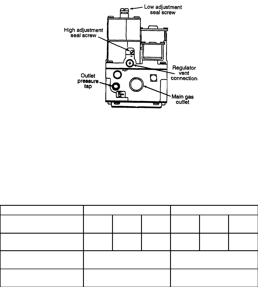
Figure 23: Outlet view of two-stage, automatic gas control valve
b. Using a 3/32-in. hex key (or Allen wrench), turn the inner adjustment screw clockwise to
increase, or counterclockwise to decrease, the gas pressure (and gas flow) to the main
burner.
c. Replace the cap screw and tighten it firmly to prevent gas leakage.
d. Referring to Table 5, measure the gas pressure and to confirm it has been adjusted to within
the allowable range. Repeat adjustments (a) through (c), as required.
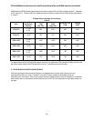
Table 5 Design Gas Pressures for each Furnace Model Series,
Operating Mode, and Type of Fuel.
Fuel Gas Type Propane Natural
Operating Mode and
Model Series
High Fire
CHX Low
Fire
CDX Low
Fire
High Fire
CHX Low
Fire
CDX Low
Fire
Normal Manifold
Pressure (in. W.G.)
10.0 ± 0.3 4.8 ± 0.3 5.6 ± 0.3 3.5 ± 0.3 1.8 ± 0.3 2.0 ± 0.3
Maximum Gas Supply
Pressure (in. W.G.)
14.0 14.0
Minimum Gas Supply
Pressure (in. W.G.)
11.0 4.5
13. Adjust the room thermostat so the burner will operate on high fire only.
NOTICE: There is a 30 second delay before the gas control will step up to high fire.
14. To obtain an accurate manifold gas pressure reading, the main burner must be cycled on and off
several times to stabilize the gas control valve pressure regulator diaphragm.
15. Allow the burner to operate for at least 3 minutes before taking gas pressure readings.
16. Using a pressure gauge, measure the burner manifold gas pressure.