33
RDVN Series Direct Vent Gas Fireplace
20007628
Unit Adjustment
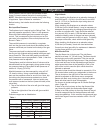
Once installed, the unit should be operated at least
three (3) times to ensure that all is in working order.
NOTE: Manufacturing oils will smoke during initial firing
of appliance. Open windows for ventilation.
Before leaving, the installer should make the following
checks:
Btu Input/Gas Pressure
The fireplace input is marked on the Rating Plate. The
gas inlet pressure specified in Table 1 is the pressure
where the field-installed gas line connects to the gas
control. This is measured at the inlet test port on the
gas valve in the appliance. Ensure that pressure is as
shown in Table 1.
The manifold pressure is controlled by a regulator
built into the gas control and should be checked at the
pressure outlet test port located on the body of the gas
valve.
The pressure should be checked with the appliance
burning on high (highest setting) and all other gas appli-
ances turned on. One must then read the manometer
and if pressures are not as specified in Table 1, then the
inlet pressure must be adjusted.
The appliance and its individual shut-off valve must be
disconnected from the gas supply piping system during
any pressure testing of the system at test pressures in
excess of 1/2 psig (3.5 KPa).
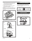
Manifold pressure can be measured by using a 5/16”
I.D. hose or tubing. Using a small blade screwdriver,
back out the pressure screw for one full turn. Next, slip
the tubing over the pressure tap extension to check
the pressure with a manometer. Inlet and outlet pres-
sure taps are located on the front (lower left side) of the
valve body.
1. Tap on the left side of the valve will give inlet supply
pressure.
2. Tap on the right side of the valve will give manifold
pressure.
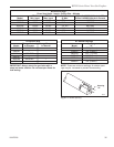
Pressure ranges are as listed below:
Table 1
Gas Supply Pressure (inches w.c.)
Minimum Normal Maximum
Natural Gas 4.5” 7.0” 14.0”
LP (Propane) 10.8” 11.0” 14.0”
Manifold Pressure (inches w.c.)
Normal (HI) Normal (Low)
Natural Gas 3.5” 1.6”
LP (Propane) 10.0” 6.3”
High Altitude
When installing this fireplace at an elevation between 0
and 2000 feet (0 - 610 m) in the USA and 0 and 4500
feet (0 - 1370 m) in Canada the input rating does not
need to be reduced.
When installing this fireplace at an elevation above
2,000 feet (in the United States), it may be necessary to
decrease the input rating by changing the existing burn-
er orifice to a smaller size. Input should be reduced
four percent (4%) for each 1,000 feet above sea level,
unless the heating value of the gas has been reduced,
in which case this general rule will not apply. To identify
the proper orifice size, check with the local gas utility.
When installing this fireplace at an elevation above
4,500 feet (in Canada), check with local authorities.
Consult your local gas utility for assistance in determin-
ing the proper orifice for your location.
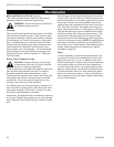
Main Burner/Pilot
The pilot flame size is factory set. The pilot flame
should be at least 1¹⁄₂” (38 mm) long. The flame should
be impinging on the pilot generator. Pilot size can be
adjusted through the pilot adjust screw. If the pilot flame
is too small and can not be adjusted through the pilot
adjust screw then there is the possibility of dirt in the
pilot orifice in which case the pilot orifice should be
cleaned or replaced.
The main burner should be allowed to operate for 15 to
20 minutes before making any adjustment to the burner.
The air shutter on the right front of the main burner
should be adjusted so that there are no orange/red
flames with dark sooty looking tips. A luminous yellow
flame with blue base is what is acceptable.
For burner air shutter settings see Air Shutter Settings
chart. (Page 35)
If there is too much primary air then the flame will be
very blue with yellow tips and smaller flame height.
If there is too little primary air then the flame will be yel-
low with orange/red tips on the back flames with dark
sooty elongated tips. In this condition the glass and logs
could show signs of soot accumulation within 10 to 20
minutes.


