LEADS Addendum
6 05780A DCN6493
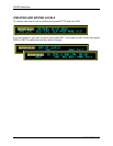
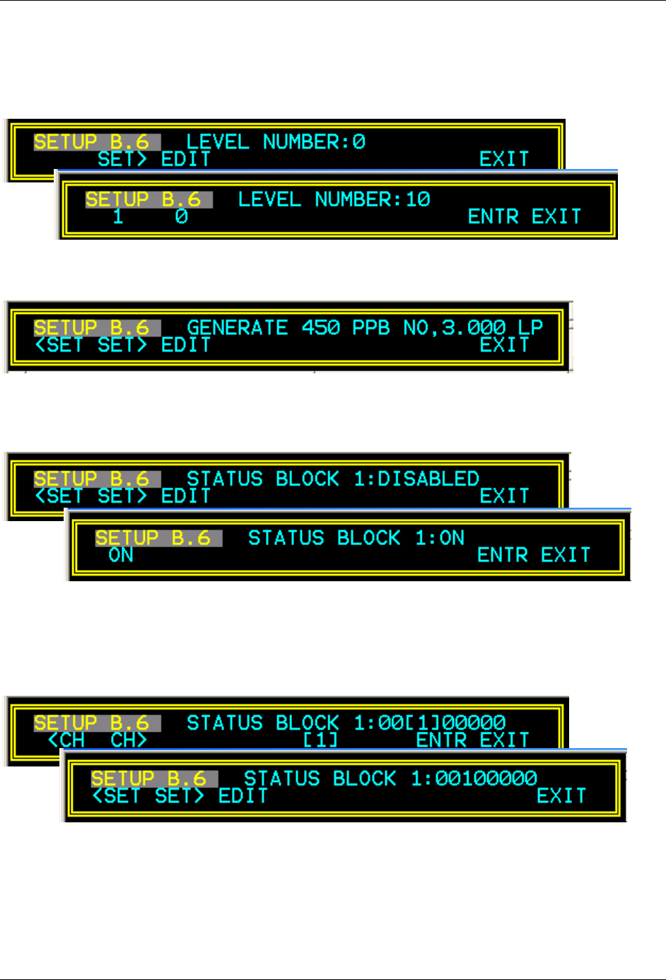
If you are creating a new level, then you will be prompted to assign the action to a level (0-99).
Press the EDIT button and then the buttons below the 0 and 10’s to select the level you wish to
use, then ENTR to store the level and level number.
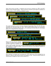
At this point you will have set the type of action, the type of gas and the flow rate out of the
analyzer for the new or modified level.
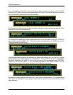
To configure the status block, which determines which of the rear panel CONTROL OUTPUTS
are energized, press the SET> key. If the status block is disabled press the EDIT key, then the
ON key, and then the ENTR key.
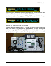
Edit the status block bit pattern by selecting the appropriate bit using the <CH and CH> buttons
and by pressing the button below the [1], or [0] button. Press ENTR to store the configuration.
The Most Significant Bit (MSB) is the first bit on the left and corresponds with CONTROL
OUTPUT-1 on the rear panel. In turn the MSB corresponds with VALVE DRIVE-1 on the
optional external valve driver option attached to the calibrator’s rear panel.
To select the second status block press SET> and follow the steps above. The second status
block does not correspond to any physical output but is used to communicate status over the
serial data port.


