


[4] Contents Of The Duct Smoke Detector Kit
1. Complete housing base and cover assembly
2. Two #10 x 1
1
/4″ sheet metal screws for mounting
3. Two sampling tube filters
4. One test magnet
5. Drilling template
6. Two foam gaskets
7. Four #6-self tapping mounting screws for the metal
sampling tube and optional exhaust tube extension
8. One sampling tube end cap
9. One plastic sampling tube
10. One #8 self-tapping screw for the plastic sampling tube
NOTE: For ducts over 1
1
⁄2 feet, longer sampling tubes must
be ordered to complete the installation. They must
be the correct length for the width of the duct
where they will be installed. See Table 1 on page
3 to determine the inlet tube required for different
duct widths.
[5] Installation Sequence
[5.1] Verify Duct Air Flow Direction And Velocity
Model DH100ACDCLP detectors are designed to be used in
air handling systems having air velocities of 100 to 4000
feet per minute. Be sure to check engineering specifications
to ensure that the air velocity in the duct falls within these
parameters. If necessary, use a velocity meter (anemom-
eter) to check the air velocity in the duct.
[5.2] Drill The Mounting Holes
Remove the paper backing from the mounting template
supplied. Affix the template to the duct at the desired
mounting location. Make sure the template lies flat and
smooth on the duct. Center punch holes A and B. Drill the
holes as indicated on the template.
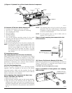
[5.2.1] Sampling Tube Installation for Ducts Less
Than 1
1
⁄2 Feet Wide (see Figure 2)
1. Remove the front cover.
2. Slide the plastic sampling tube into the housing bushing.
3. Align the holes in the bushing with the holes in the
sampling tube. Make sure there are 6 exposed holes on
the plastic sampling tube. Secure with the #8 self-tapping
screw into the bottom of the permanent tube (shown in
Fig. 2).
NOTE: The sampling tube end cap is critical to the proper
operation of the duct smoke detector. The end cap
is needed to create the proper air flow to the sensor
of the duct smoke detector.
NOTE: For ducts greater than 1
1
⁄2 feet in width, refer to
sections [5.4.1] and [5.4.2].
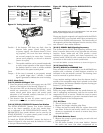
Figure 2. Plastic sampling tube connected to duct
smoke detector:
H0110-00
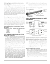
[5.3] Secure The Detector Housing To The Duct
Slide the foam gaskets over the tube bushings as shown in
Figure 3. Use the two 1
1
/4″ long sheet metal screws to screw
the detector housing to the duct.
CAUTION: Do not overtighten the screws.
Figure 3. Installation of foam gaskets over sampling
tube bushings:
SCREW HOLES FOR
ATTA
CHING HOUSING
TO
DUCT WORK.
H0107-00
D200-14-00 2 I56-0084-08R
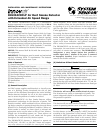
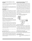
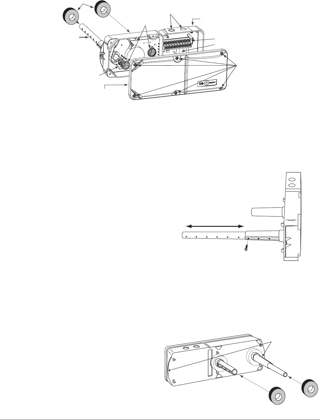
[3] Figure 1: Exploded View of Duct Smoke Detector Components
FOAM
GASKETS
METAL
SAMPLING TUBE
SAMPLING TUBE
FILTERS
DETECTOR
COVER
DETECTOR BOARD
CONDUIT HOLES
DETECTOR
HOUSING
TERMINAL STRIP
POWER BOARD
COVER MOUNTING
SCREWS
H0165-00