


NOTE: DIAGRAMS & ILLUSTRATION NOT TO SCALE.
5
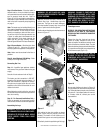
PREINSTALLATION
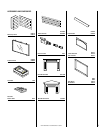
Check that all listed parts have been received.
Carefully inspect the heater case and contents
for shipping damage and immediately inform
the dealer from whom you purchased the gas
fireplace if any damage is found.
The appliance is shipped with all gas controls
and components installed and pre-wired. Re-
move the shipping carton, exposing the op-
tional (if installed) front glass door frame.
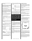
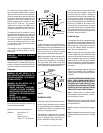
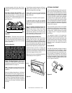
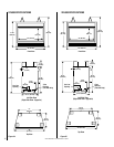
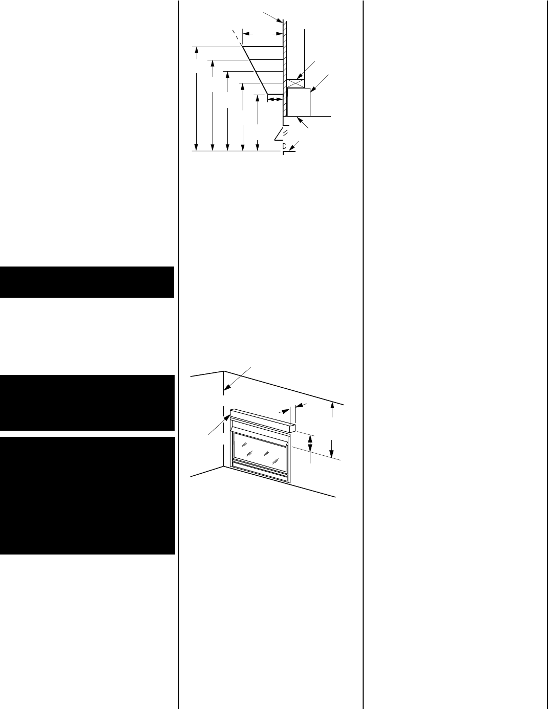
Ensure the minimum clearances shown in
Fig-
ures 2 and 3
are maintained.
Minimum clearance to combustibles are:
Appliance: side and back - 0"
floor - 0"
adjacent wall - 6"
ceiling - 37-1/2” (953 mm)
37-1/2" Min.
to Ceiling
(953 mm)
(See Fig. 2)
6" Clearance
to Combustible
Side Wall
Max. Projection (See Fig. 2)
Combustible
Mantel
Combustible
Finished Wall
Materials
Top of Appliance
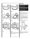
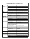
VF Series
12"
( mm)
2-1/2"
( mm)
8"
( mm)
26"
( mm)
Top of Door Frame
Spacer
6''
8''
10''
22-1/2"
( mm)
18-5/8"
( mm)
14-1/2"
( mm)
Header
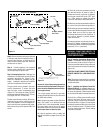
Remove wood slats and remove and discard
the wood slat mount brackets. Loosen and
remove the three (3) 1/4"-20 x 1" Phillips pan
head screws at the three (3) tabs located along
the door frame top edge. Tilt the glass door
frame assembly outward and disengage the
three (3) tabs along the bottom of the door from
the three (3) brackets at the bottom of the
firebox opening. Remove the door and set the
panel aside protecting it from inadvertent dam-
age. Retain the three (3) screws for use on
reassembly. Remove the logs, packaged inside
the firebox, and also set aside.
Check Gas Type
This appliance can only be connected to the gas
type specified on the appliance data plate. This
appliance can not be modified in the field for a
different gas type. If the gas type to be used is
not the one specified contact the dealer to
obtain the correct gas appliance.
Note: Illustrations shown in this manual reflect
“typical” installations with nominal dimensions
and are for design and framing reference only.
Actual installations may vary due to individual
design preferences. However, always maintain
minimum clearances to combustible materials
and do not violate any specific installation re-
quirements.
Note: The following steps represent the normal
sequence of installation. Each installation is
unique, however, and might require a different
sequence.
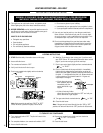
CAUTION: HEATERS CREATE WARM AIR CUR-
RENTS. THESE CURRENTS MOVE HEAT TO
WALL SURFACES NEXT TO HEATER. INSTALL-
ING HEATER NEXT TO VINYL OR CLOTH WALL
COVERINGS OR OPERATING HEATER WHERE
IMPURITIES IN THE AIR (SUCH AS TOBACCO
SMOKE) EXISTS, MAY DISCOLOR WALLS.
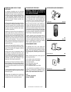
Step 1. Position heater in desired location
(freestanding, onto surround base or into pre-
pared framing) and secure.
Step 2. Plumb gas line. (Gas connections should
only be performed by an experienced, licensed/
certified tradesman.)
Step 3. Assemble logs and test flame appear-
ance.
Step 4. Complete finish wall material, surround
and optional hearth extension to your individual
taste.
Figure 3
Figure 2
A hearth extension is not required with this
appliance. If a hearth extension is used, do not
block the lower control compartment door. Any
hearth extensions used is for appearance only
and does not have to conform to standard
hearth extension installation requirements.
Note: Combustible wall finish materials and/or
surround materials must not be allowed to
encroach the area defined by the appliance
front face (black sheet metal). Never allow
combustible materials to be positioned in front
of or overlapping the appliance front face.
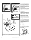
To provide for the lowest possible shelf sur-
face, combustible materials used to support a
utility shelf directly above these appliances
should be positioned just above the appliance
top spacers. The minimum height from the
base of the VF5000 to the underside of com-
bustible materials used to construct a utility
shelf is 34-1/2” (876 mm). The minimum
height from the base of the VF6000 to the
underside of combustible materials used to
construct a utility shelf is 39-1/2” (1003 mm).
The appliance should be mounted on a fully
supported base extending the full width and
depth of the unit. The appliance may be located
on or near conventional construction materi-
als. However, if installed on combustible mate-
rials, such as carpeting, vinyl tile, etc., a metal
or wood barrier covering the entire bottom
surface must be used.
If the appliance is to be elevated above floor
level, a solid continuous platform must be
constructed.
WARNING: MAINTAIN MINIMUM
CLEARANCES.
Do not install in the vicinity of gasoline or other
flammable liquids. The heater must be kept clear
and free from these combustible materials and
may not be located near where they are stored.
Clearances
WARNING: DO NOT INSTALL VF SE-
RIES UNVENTED ROOM HEATERS IN
SLEEPING QUARTERS, OR IN RECRE-
ATIONAL VEHICLES.
WARNING: DO NOT INSTALL THE VF
UNVENTED ROOM HEATER:
• WHERE CURTAINS, FURNITURE,
CLOTHING OR OTHER FLAMMABLE
OBJECTS ARE LESS THAN 42" FROM
THE FRONT OF THE UNVENTED ROOM
HEATER.
• IN HIGH TRAFFIC AREAS.
• IN WINDY OR DRAFTY AREAS.