


NOTE: DIAGRAMS & ILLUSTRATIONS ARE NOT TO SCALE.
16
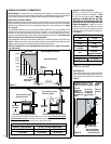
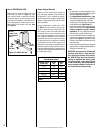
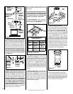
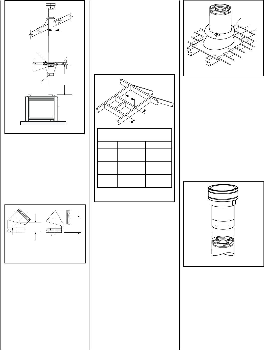
v SV4.5VF
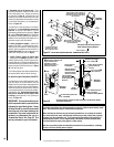
Firestop / spacer
uSV4.5SU
Support Strap
8 ft. (2.4 M)
Maximum
uSV4.5SP
Support Plate
Ceiling Framing
uSecured
to Vent with
Appropriate
Fasteners
1” (25.4 mm)
Minimum
Clearance to
Combustibles
vWhen using
secure Flex, use
Firestop/Spacer
SF4.5VF
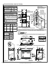
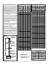
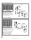
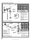
Framing Dimensions for Roof
Inches (millimeters)
Pitch C D
0/12 10-1/2 in.
(267 mm)
10-1/2 in.
(267 mm)
6/12 10-1/2 in.
(267 mm)
12 in.
(305 mm)
12/12 10-1/2 in.
(267 mm)
17-3/4 in.
(451 mm)
Figure 24 - Roof Framing
C
D
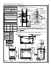
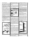
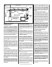
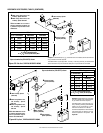
Figure 25
Storm
Collar
Figure 26
Flashing
7-5/8”
(194 mm)
4-13/16
(122 mm)
(206 mm)
If the vent system extends more than 5 feet
(1.5 m) above the roof flashing, stabilizers may
be necessary. Additional screws may be used
at section joints for added stability. Guide wires
may be attached to the joint for additional sup-
port on multiple joint configurations.
G. Continue installation of horizontal / inclined
sections - Continue with the installation of the
straight vent sections in horizontal / inclined run
as described in Step C. Install support straps
every 5 feet (1.52 m) along horizontal / inclined
vent runs using conventional plumber’s tape.
See Page 19, Figure 32. It is very important
that the horizontal / inclined run be maintained
in a straight (no dips) and recommended to
be in a slightly elevated plane, in a direction
away from the fireplace of 1/4" rise per foot (20
mm per meter) which is ideal, though rise per
foot run ratios that are smaller are acceptable
all the way down to at or near level.
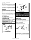
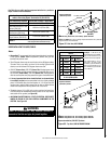
F. Change vent direction to horizontal / inclined
run - At transition from or to a horizontal / in-
clined run, install the SV4.5E45 and SV4.5E90
elbows in the same manner as the straight vent
sections. The elbows feature a twist section to
allow them to be routed about the center axis
of their initial collar section to align with the
required direction of the next vent run element.
Twist elbow sections in a clockwise direction
only so as to avoid the possibility of unlocking
any of the previously connected vent sections
(see Figure 23).
Use a carpenter’s level to measure from a
constant surface and adjust the support straps
as necessary.
It is important to maintain the required clear-
ances to combustibles: 1" (25 mm) at all sides
for all vertical runs; and 3" (76 mm) at the top,
1" (25 mm) at sides, and 1" (25 mm) at the
bottom for all horizontal / inclined runs.
H. Frame roof opening - Identify location for
vent at the roof. Cut and/or frame opening per
Roof Framing Chart and Figure 24.
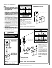
Figure 23
Swivel Joint
(360° swivel)
SV4.5E45
45° Elbow)
Swivel Joint
(360° swivel)
SV4.5E90
90° Elbow)
SV4.5FA or
SV4.5FB Flashing
and SV4.5SC
Storm Collar
SV4.5CGV-1
Termination
8-1/8"
K. Install the vertical termination - The final
Step involves installation of the SV4.5CGV-1
Vertical Termination. Extend the vent sections
to the height as shown in the "Vertical vent
termination section" (Page 6, Figure 4B). The
SV4.5CGV-1 Vertical Termination (Figure 26)
can be installed in the exact same fashion as
any other Secure Vent™ section. Align the
termination over the end of the previously
installed section, adjusting the radial alignment
until the four locking dimples of the termination
are aligned with the inlets of the four incline
channels of the last vent section. Push the ter-
mination down until it fully engages, then twist
the termination clockwise running the dimples
down and along the incline channels until they
are seated at the end of the channels.
I. Install the roof flashing - Extend the vent
sections through the roof structure. Install the
roof flashing over the vent section and position
such that the vent column rises vertically (use
carpenters level - see Figure 25). Nail along
perimeter to secure flashing or adjust roofing
to overlap the flashing edges at top and sides
only and trim where necessary. Seal the top
and both sides of the flashing with waterproof
caulking.
J. Install the storm collar - Install the storm
collar, supplied with the flashing, over the vent /
flashing joint. See Figure 25. Loosen the storm
collar screw. Slide collar down until it meets
the top of the flashing. Tighten the adjusting
screw. Apply non-combustible caulking or
mastic around the circumference of the joint
to provide a water tight seal.
Figure 22