


NOTE: DIAGRAMS & ILLUSTRATIONS ARE NOT TO SCALE.
25
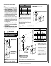
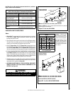
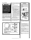
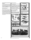
Figure 43 - Millivolt Wiring Diagram
Field Wired
Factory
Wired
TH
TP
TH
TP
* Optional
Control Switch
Thermopile
Schematic
Representation
Only
• If any of the original wire as supplied must be
replaced, it must be replaced with Type AWM
105 C - 18 gage wire.
* Optional Kits Installed - ON/OFF wall switch, unit mounted burner ON/OFF switch, wall thermostat or
remote control.receiver.
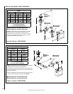
HT
PT
HT
PT
*
* Twist wires together to operate unit
solely by manipulating the gas valve
control knob; or connect wires to
optional control switch (wall switch,
remote control or wall thermostat to
operate unit.
CAUTION: Label all wires prior to disconnec-
tion when servicing controls. Wiring errors can
cause improper and dangerous operation.
ATTENTION: Au moment de l'entretien des
commandes, étiquetez tous les fils avant de
les débrancher. Des erreurs de cáblage peu-
vent entraîner un fonctionnement inadéquat
et dangereux.
Verify proper operation after servicing.
S'assurer que l'appareil fonctionne adé-
quatement une fois l'entretien terminé.
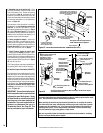
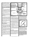
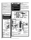
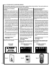
CAUTION
Ground supply lead must be con-
nected to the wire attached to the
green ground screw located on the
outlet box. See Figure 46. Failure to
do so will result in a potential safety
hazard. The appliance must be
electrically grounded in accordance
with local codes or, in the absence of
local codes, the National Electrical
Code, ANSI/NFPA 70-latest edition.
(In Canada, the current CSA C22-1
Canadian Electrical Code).
Step 4. FIELD WIRING
Refer to Section A for millivolt appliances and
Section B for electronic appliances. The gas
valve is set in place and pre-wired at the factory
on both models.
A. Millivolt Wiring (See Figure 43):
1. Install and wire in the burner control switch.
Install either "a" or "b" below, NOT BOTH
(installing both may result in improper burner
operation).
a. Optional OFF/ON Switch - Install the OFF/
ON burner control switch (rocker switch)
as shown in Figures 43 and 44.
b. Optional Wall Switch, Wall Thermostat
Or Remote Control Receiver - Install snap
bushing (provided in Electrical Outlet
Kit - See Figure 44) into control switch
knock-out in side panel (see Figures 12
and 13 on Pages 10 and 11). Wire the
optional control switch within the millivolt
control circuit (as shown in Figure 43)
using the 15 feet of 2 conductor wire
supplied (route wires through the snap
bushing to the optional control switch).
Mount the optional control switch or wall
thermostat in a convenient location on a
wall near the fireplace.
CAUTION: Do not connect optional control
switch to 120V power supply.
2. Install the junction box and receptacle outlet
to the left of the valve in the front (for optional
blower kit). See junction box and receptacle
outlet as explained in steps 1-11 for (B)
Electronic Wiring (on this page).
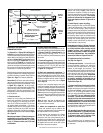
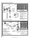
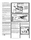
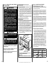
Gas
Valve
Control Compartment
Access panel
OFF/ON
Switch
TP TH
TH
Install OFF/ON Switch
(millivolt models)
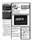
1. Connect the 2 wires (provided in Electrical
Outlet Kit) to the TP/TH and TH terminals
on valve.
2. Pass the 2 wires through the opening where
OFF/ON switch will be installed (left of piezo,
below valve).
3. Connect the two wires to the OFF/ON
Switch.
OFF/ON
Switch
Connect
wires to
terminals
4. Press the OFF/ON switch into bracket as
shown below (it will snap into place).
Figure 44
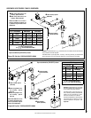
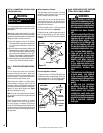
B. Electronic Wiring (See Figures 45 and
46)
Notes:
• The electronic appliance must be connected
to the main 120 VAC power supply.
•The junction box can be installed in any of the
4 outside corners of the control compartment
(it can be found factory installed in the right
front corner viewed from the valve access side
(where it should be reinstalled if an optional
blower kit is installed).
1. Route a 3-wire, 120 VAC, 60 Hz, 1 ph power
supply to the location on appliance where
junction box is to be installed.
2. Open the control compartment access panel
(see Control Compartment Access Instruc-
tions on Page 27).
3. Remove the junction box/outlet receptacle
assembly by removing the securing screw at
the front right corner of the unit. See Figure
45.
4. Remove the outlet receptacle from the
junction box by removing the two securing
screws.