


12
NOTE: DIAGRAMS & ILLUSTRATIONS ARE NOT TO SCALE.
SUPERIOR
®
DIRECT-VENT GAS FIREPLACES • MODELS SLDVT-30/35/40/45 • CARE AND OPERATION INSTRUCTIONS
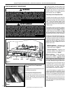
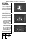
Figure 7
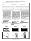
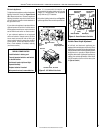
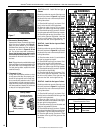
4. Placement of Glowing Embers -
Separate the Embers (rockwool) into pieces
about the size of a quarter (see Figure 8).
Keep the pieces fluffed up, not matted.
Distribute these pieces over the surface of
the burner, as shown in Figures 9, 10 and
11. Do not use more than is necessary.
Ensure that the main burner slots remain
uncovered by the ember material. Position
the embers on the small holes of the ember
bed area.
Note: This appliance is provided with enough
Glowing Embers for several applications, do
not use all that is in a new bag at one time.
For best glowing effect, replace the ember
material annually.
5. Placement of Logs -
All logs that have locating notches or slots
to help ensure that they are properly posi-
tioned. All top logs that rest on lower logs,
do so over notches, indents or nubs. Proper
log placement is critical to prevent sooting.
Logs should be placed in the gaps between
the flame peaks and should be positioned
so they do not impinge the flames.
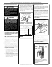
Volcanic Stone
Place Volcanic
Stone As Shown
REFERENCE
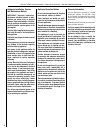
Firebox Accessories / Parts
Cat. No. Model No. Description
88L53 FGE Bag of Glowing Embers
80L42 FDVS
Bag of Decorative
Volcanic Stone
Glowing Embers
Bag of Glowing
Embers (rockwool)
Separate into Quarter
Size (separate) Pieces
Figure 8
WARNINGS
•
DO NOT attempt to install the
logs until the appliance instal-
lation has been completed, the
gas line connected and tested
for leaks and the initial burner
operation has been checked out.
• The size and position of the log
set was engineered to give the
appliance a safe, reliable and
attractive flame pattern. Any
attempt to use a different log
set in the fireplace will void
the warranty and will result in
incomplete combustion, soot-
ing, and poor flame quality.
• Logs get very hot and will
remain hot up to one hour
after gas supply is turned off.
Handle only when logs are
cool. Turn off all electricity
to the appliance before you
install grate, volcanic stone,
vermiculite, embers and logs.
• This appliance is not designed
to burn wood. Any attempt to
do so could cause irreparable
damage to appliance and prove
hazardous to your safety.
• If logs are not installed accord-
ing to the log installation
instructions, flame impinge-
ment and improper combustion
could occur and result in soot
and/or excessive production
of carbon monoxide (CO), a
colorless, odorless, toxic gas.
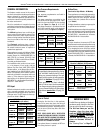
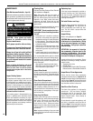
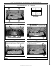
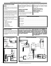
SLDVT-30 and 35 - Install the four logs as
Follows:
Carefully position the ceramic fiber logs over
the burner as shown in Figure 9. Logs should
be placed in the order shown and per the fol-
lowing instructions.
1. Place the left front log (1) as shown. Posi-
tion it on the two left front log brackets.
2. Place the right front log (2) as shown.
Position it on the two right front log brackets.
3. Place the left rear log (3) as shown. Position
it on the upper and lower left rear log brackets.
4. Place the right rear log (4) as shown. Posi-
tion it on the right rear log bracket. Note that
the hole on the bottom of the right rear log
rests over the "Nub" on the right front log.
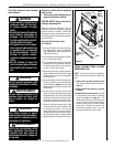
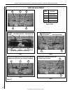
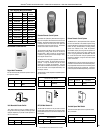
SLDVT-40 - Install the four logs and Ember
Chunk as Follows:
Carefully position the ceramic fiber logs over
the burner as shown in Figure 10. Logs should
be placed in the order shown and per the fol-
lowing instructions.
1. Place the ember chunk (1) over the tab on
the rear log support as shown.
2. Place the left front log (2) as shown. Posi-
tion it on the two left front log brackets.
3. Place the right front log (3) as shown.
Position it on the two right front log brackets.
4. Place the left rear log (4) as shown. Position
it on the left rear log bracket.
5. Place the right rear log (5) as shown. Posi-
tion it on the right rear log bracket. Note that
the hole on the bottom of the right rear log
rests over the "Nub" on the right front log.
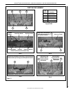
SLDVT-45 - Install the five logs as Follows:
Carefully position the ceramic fiber logs over
the burner as shown in Figure 11. Logs should
be placed in the order shown and per the fol-
lowing instructions.
1. Place the left front log (1) as shown. Posi-
tion the holes on the bottom of the log on the
two left front log brackets.
2. Place the right front log (2) as shown.
Position the holes on the bottom of the log on
the two right front log brackets.
3. Place the center log (3) over the center and
right rear log brackets as shown.
4. Place the left rear log (4) as shown. Position
the holes on the bottom of the log on the left rear
log brackets. Log also rests on center log (3).
5. Place the right rear log (5) as shown. Rest
the bottom of the log over the groove on the
center log.