


6
NOTE: DIAGRAMS & ILLUSTRATIONS NOT TO SCALE.
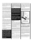
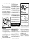
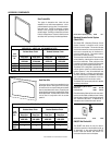
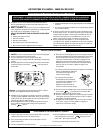
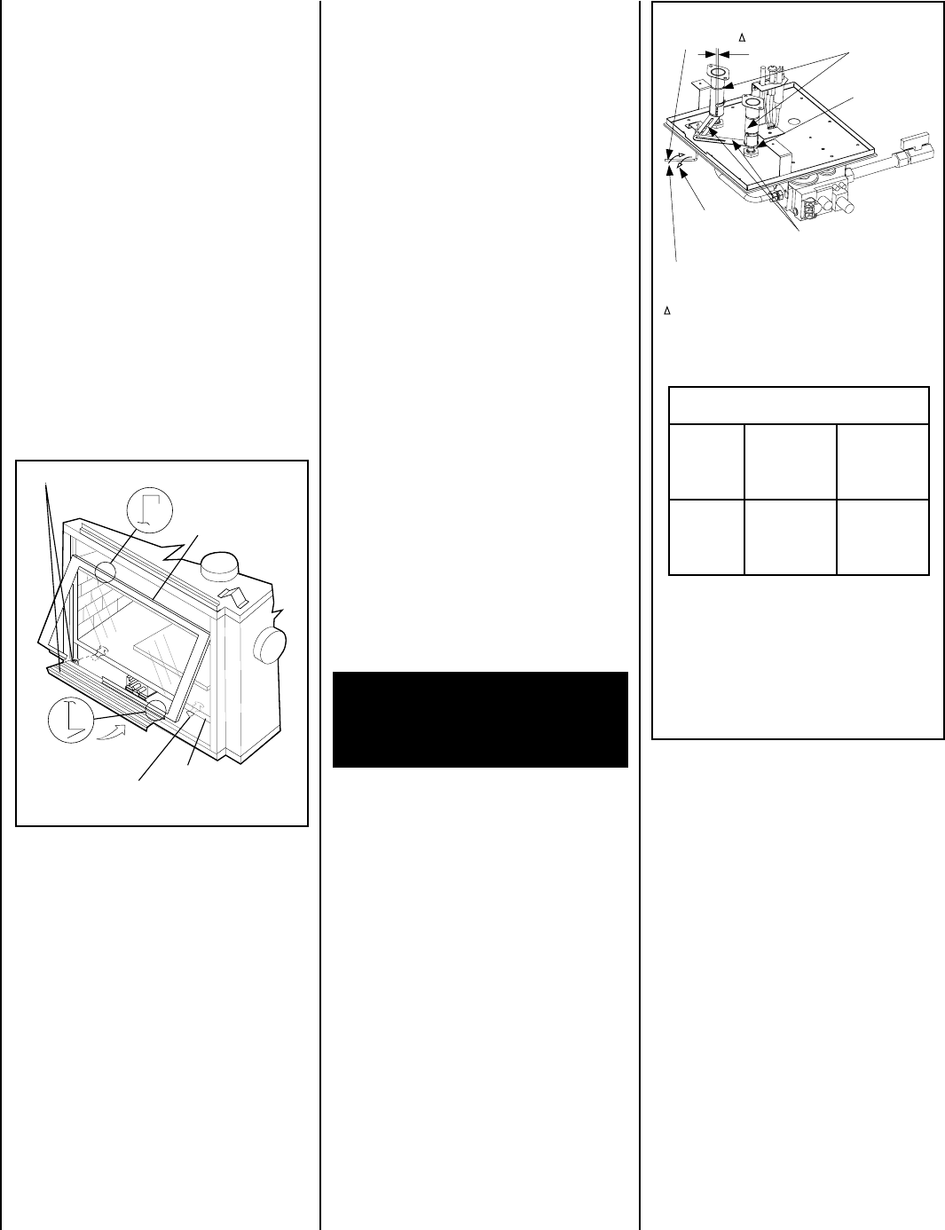
Figure 5
Adjustment Rod Positions (when viewed
from above):
*Natural Gas
- fully clockwise
**Propane
- fully counter clockwise
*** Settings shown are for each burner.
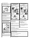
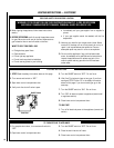
Refer to
Figure 4
and remove the front glass
enclosure panel as follows:
1. Remove the top louver assembly or radiant
panel.
2. Open the control compartment access panel.
To open the control compartment access panel,
actuate the spring-loaded magnetic catches
securing the panel, by gently depressing the
outer top corners of the panel until the catches
"pop" the door free, allowing it to swing out and
down to open.
3. Locate the two (2) latches at the top of the
control compartment. To disengage the two
latches from the bottom vee-flange of the glass
enclosure panel, reach for the handles located
towards the back of the latches and pull the
handles down toward the front of the unit.
4. Swing the bottom of the door out and raise
it slightly to lift the top flange of the door frame
away from the appliance.
To install the front glass enclosure panel,
proceed as follows:
1. Visually inspect the gasket on the backside
of the panel. The gasket surface must be clean,
free of irregularities and seated firmly.
2. Position the glass enclosure panel in front of
the firebox opening at a 45 degree angle and
engage the top flange over the lip at the top of
the firebox opening.
3. Swing the glass enclosure panel down and
back. Ensure the gasket seats evenly as the
panel draws shut. Engage the Vee-flange at the
bottom of the panel with the latches and close
the latches to secure the panel.
4. Reinstall the top louver assembly or radiant
panel.
Burner Adjustments
The following paragraphs address burner ad-
justment concerns and procedures.
Flame Appearance and Sooting
Proper flame appearance is a matter of taste.
Generally most people prefer the warm glow of
a yellow to orange flame. Appliances operated
with air shutter openings that are too large will
exhibit flames that are blue and transparent.
These weak, blue and transparent flames are
termed anemic. If the air shutter opening is too
small sooting may develop.Sooting is indi-
cated by black puffs developing at the tips of
very long orange flames. Sooting results in
black deposits forming on the logs, appliance
inside surfaces and on exterior surfaces adja-
cent to the vent termination.
Sooting is caused by incomplete combustion in
the flames and a lack of combustion air entering
the air shutter opening. To achieve a warm
yellow to orange flame with an orange body that
does not soot, the shutter opening must be
adjusted between these two extremes. No smoke
or soot should be present. Reposition the log set
if the flames impinge on any part of it.
If the log set is properly positioned and
sooting conditions exist, the air shutter open-
ing on the main burner tube should be ad-
justed. Normally, the more offsets in the vent
system, the greater the need for the air shutter
to be opened further.
ENSURE THAT ALL GLASS PANELS ARE IN
PLACE AND SEALED DURING ADJUSTMENT.
The adjustment rod and associated adjustable
air shutter is patented technology. Flame ad-
justments can be made quickly and accurately
to taste without the need of disassembling the
appliance and waiting for 15 minutes after each
adjustment.
Propane models may exhibit a flame pattern
that may candle or appear stringy. If this is
problematic or persists as the appliance is
continually operated, adjust the air shutter
closed as described in the previous paragraphs.
Operate the appliance for a period of time as the
effect diminishes, ensuring that the appliance
does not develop sooty flames.
When satisfied that the appliance operates prop-
erly, proceed to finish the installation. Leave the
control knob in “ON” position and turn the
remote switch “OFF.” Close the lower control
compartment access panel.
Adjustment
CAUTION: THE ADJUSTMENT ROD AND
NEARBY APPLIANCE SURFACES ARE HOT.
EXERCISE CAUTION TO AVOID INJURY WHILE
ADJUSTING FLAME APPEARANCE.
To adjust the flame, rotate the adjustment
rod (located in the lower control area) coun-
terclockwise to increase or clockwise to re-
duce the air shutter opening. Adjust the air
shutter to the recommended setting as
shown in
Figure 5
. Allow the burner to oper-
ate for at least 15 minutes. Observe the flame
continuously. If it appears weak or sooty as
previously described, adjust the air shutter
by rotating the adjustment rod until the flame
appearance is as desired.
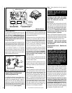
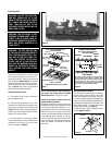
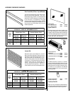
Figure 4 CDST Shown
Glass Door Latch
Control Compartment Access Panel and Hinge
Front Glass
Enclosure Panel
Firebox Floor
Bottom Vee-flange
Glass Door Frame
Top Flange
Glass Door Frame
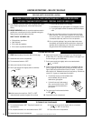
RENRUBNIAM***
GNITTESRETTUHSYROTCAF
sledoM
saGlarutaN
sehcni
)mm(
enaporP
saG
sehcni
)mm(
TSDC
FPDC
RCDC
LCDC
OWT*
8/1)3(
STOLS
OWT**
61/11)71(
STOLS
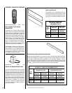
Air Shutter
Adjusting
Rod
Air Shutter
Adjusting
Arms
Orifice
Increase Shutter
Opening In This
Direction
Decrease Shutter
Opening In This
Direction
Air Shutter
Opening
Burner
Venturi
Tube
Note - Both air shutters open and close
simultaneously when the air shutter
adjusting rod is moved.
Note - Burners are omitted in this view for clarity.
WARNING: AIR SHUTTER ADJUST-
MENT SHOULD ONLY BE PERFORMED
BY A QUALIFIED PROFESSIONAL SER-
VICE TECHNICIAN.