


8
NOTE: DIAGRAMS & ILLUSTRATIONS NOT TO SCALE.
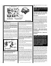
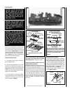
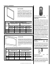
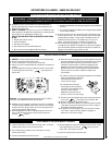
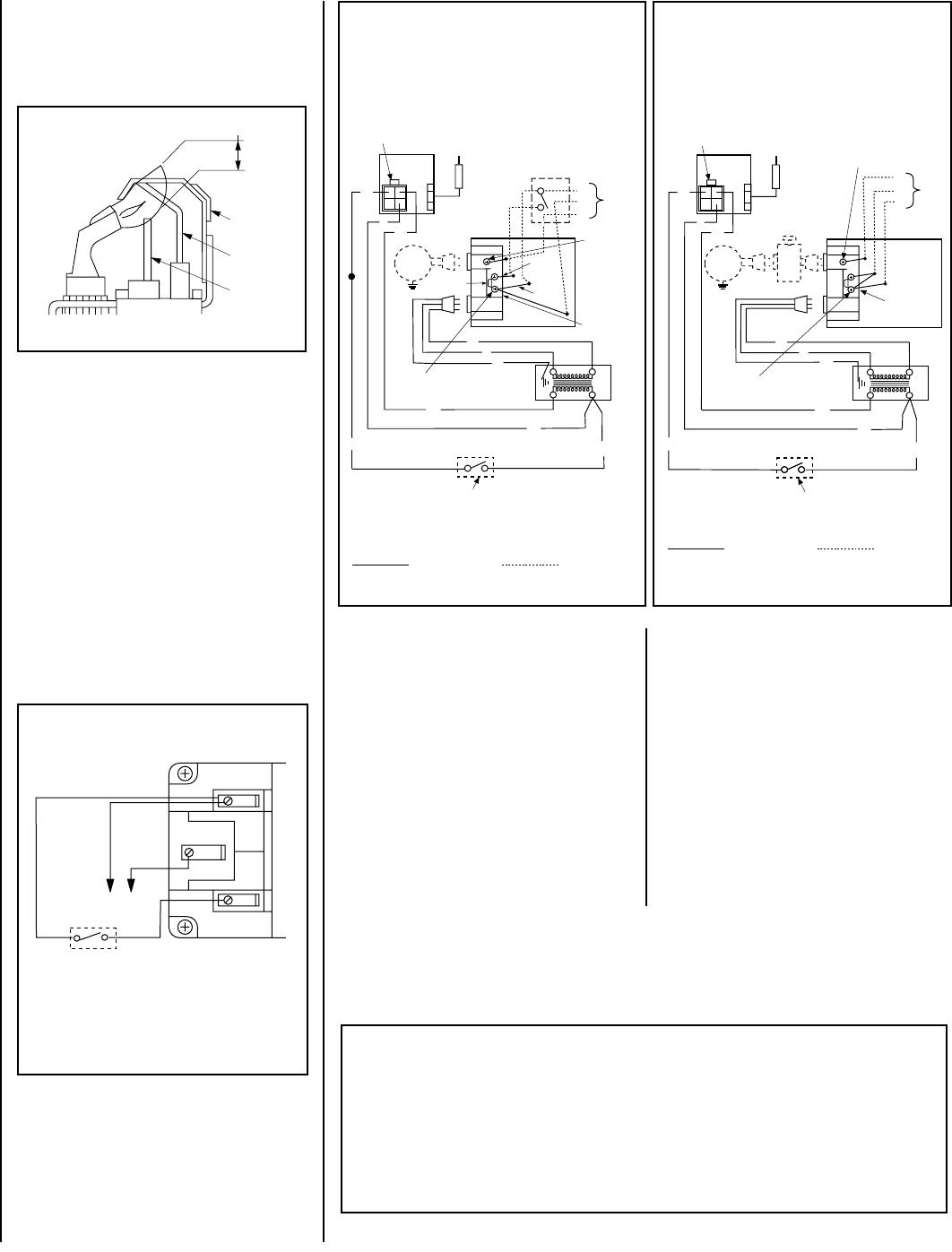
Electronic Appliance Checkout
To light the burner, refer to the lighting instruc-
tions on
page 14 and 15
. Ensure the ignitor
lights the pilot. The pilot flame should engulf the
flame sensor as shown in
Figure 10
Figure 10
With proper care and maintenance, your appli-
ance will provide many years of enjoyment. If you
should experience any problem, first refer to the
trouble shooting guide in this manual. If problem
persists, contact your Lennox distributor.
WIRING DIAGRAMS
Wiring diagrams are provided here for refer-
ence purposes only. This information is also
provided on schematics attached directly to
the appliance on a pullout panel located within
the control compartment.
CAUTION: LABEL ALL WIRES PRIOR TO DIS-
CONNECTION WHEN SERVICING CONTROLS.
WIRING ERRORS CAN CAUSE IMPROPER AND
DANGEROUS APPLIANCE OPERATION.
WARRANTY
Your gas appliance is covered by a limited twenty
year warranty. You will find a copy of the war-
ranty accompanying this manual. Please read
the warranty to be familiar with its coverage.
REPLACEMENT PARTS
A complete parts list is found at the end of this
manual. Use only parts supplied from the
manufacturer.
Normally, all parts should be ordered through
your Lennox distributor or dealer. Parts will be
shipped at prevailing prices at time of order.
When ordering repair parts, always give the
following information:
PRODUCT REFERENCE INFORMATION
We recommend that you record the following important information about your fireplace. Please
contact your Lennox dealer for any questions or concerns. For the number of your nearest Lennox
dealer, please call 800-731-8101
Your Fireplace's Model Number _______________________________________
Your Fireplace's Serial Number ________________________________________
The Date On Which Your Fireplace Was Installed __________________________
The Type of Gas Your Fireplace Uses ___________________________________
Your Dealer's Name_________________________________________________
If you encounter any problems or have any
questions concerning the installation or appli-
cation of this system, please contact your dis-
tributor, or Lennox directly:
LHP
1110 West Taft Avenue • Orange, CA 92865
1. The model number of the appliance.
2. The serial number of the appliance.
3. The part number.
4. The description of the part.
5. The quantity required.
6. The installation date of the appliance.
Retain this manual. File it with your other docu-
ments for future reference.
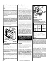
Proper Flame
Adjustment
Hot Surface
Igniter
Flame Rod
Ground
Electrode
3/8 To 1/2 Inch
(9 mm to 13 mm)
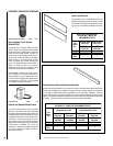
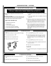
1. If any of the original wire as supplied must be replaced,
1. it must be replaced with Type AWM 105°C – 18 GA. wire.
2. 120V, 60Hz – Less than 3 amps.
BK
Junction Box
Transf.
120 V.
24 V
Factory Wired Field Wired
BL
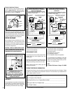
Electronic Wiring Diagram (Honeywell)
Showing the Blower Wiring for the Optional
FBK-100 and FBK-200 Kits
R
W
BL
OPT
BLOWER
G
W
*OPTIONAL
ACCESSORY
SWITCH
120
VAC.
BK
W
Gas Valve
B
R
IGNITER
PILOT
ASSEMBLY
Break Off
Tab
BK
G
*Blower speed control switch is provided in FBK200 blower kit.
Outlet Box
Green Ground
Screw
Hot side of Outlet
Schematic Representation Only
**ON/OFF Switch (Integral
with Gas Valve)
**Leave the ON/OFF switch, which is integral
with the gas valve, in the ON position.
OPTIONAL APPLIANCE-MOUNTED ON/OFF SWITCH
OR OPTIONAL WALL SWITCH
OR OPTIONAL THERMOSTAT
OR OPTIONAL REMOTE RECEIVER
Red
pigtail
Black
pigtail
White Wire
to Opposite
Side
G
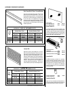
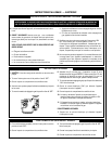
1. If any of the original wire as supplied must be replaced,
1. it must be replaced with Type AWM 105°C – 18 GA. wire.
2. 120V, 60Hz – Less than 3 amps.
BK
Transf.
120 V.
24 V
Factory Wired Field Wired
BL
Electronic Wiring Diagram (Honeywell)
Showing the Blower Wiring for the Optional
FBK-250 Kits
R
WH
BL
OPT
BLOWER
G
W
120
VAC.
BK
W
Gas Valve
B
R
IGNITER
PILOT
ASSEMBLY
BK
G
Outlet Box Green
Ground Screw
Hot side of Outlet
Schematic Representation Only
*ON/OFF Switch (Integral
with Gas Valve)
White Wire
To Opposite
Side
Optional FBK-250
Module
*Leave the ON/OFF switch, which is integral
with the gas valve, in the ON position.
G
OPTIONAL APPLIANCE-MOUNTED ON/OFF SWITCH
OR OPTIONAL WALL SWITCH
OR OPTIONAL THERMOSTAT
OR OPTIONAL REMOTE RECEIVER
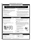
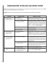
Millivolt Wiring Diagram
If any of the original wire as supplied must be replaced,
it must be replaced with Type AWM 105°C, 18 GA. wire.
Thermopile
TH
TP
TH
TP
*TWIST WIRES “A” AND “B” TOGETHER TO OPERATE UNIT
SOLELY BY MANIPULATING THE GAS VALVE CONTROL KNOB;
OR CONNECT WIRES TO OPTIONAL UNIT-MOUNTED ON/OFF
SWITCH OR WALL-MOUNTED ON/OFF SWITCH OR
THERMOSTAT TO OPERATE UNIT.
*UNIT-MOUNTED ON/OFF SWITCH (Accessory Option)
OR WALL-MOUNTED ON/OFF SWITCH (Accessory Option)
OR THERMOSTAT (Accessory Option)
OR REMOTE CONTROL RECEIVER (Accessory Option)
AB