


7
NOTE: DIAGRAMS & ILLUSTRATIONS NOT TO SCALE.
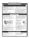
Log Placement
Figure 7
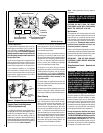
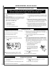
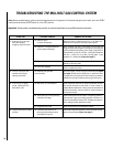
Millivolt Appliance Checkout
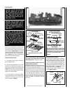
The pilot flame should be steady, not lifting or
floating. Flame should be blue in color with
traces of orange at the outer edge. The top ³⁄₈"
(10 mm) at the pilot generator (thermopile) and
the top ¹⁄₈" min (tip) of the quick drop out thermo-
couple should be engulfed in the pilot flame. The
flame should project 1" (25 mm) beyond the
hood at all three ports. See
Figure 9.
To light the burner, refer to the lighting instruc-
tions on
pages 12 and 13.
Figure 6
Figure 9
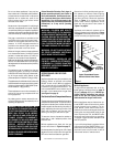
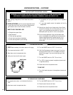
Note: If the burners have been removed for
any reason, rear burner must be installed
before front burner. See Figures 7 and 8.
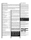
Install the unitized log set:
a - The bottom of the log set is notched to
accommodate the pilot.
b - Place the log set so that the four inner
notches on the underside of the log set fit over
the four risers located on the burner ends. See
Figure 6
. This procedure is accomplished pri-
marily by feel, as the log set masks the burner
risers as it is being installed.
c - As a final check for correct log set place-
ment, check that the four outer notches on the
underside of the log set fit over the burner
tines as indicated in
Figure 6
.
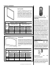
The log set, the decorative volcanic stone
and the glowing embers (rockwool) are lo-
cated inside the unit. Refer to the following
information and
Figures 6 and 7
for detailed
placement instructions for the logs, the deco-
rative volcanic stone and the glowing em-
bers.
Figure 6
also shows a typical flame
pattern for this particular appliance.
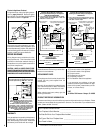
Install the decorative volcanic stone and
glowing embers (rockwool):
Spread the decorative volcanic stone on the
simulated brick floor of the firebox around the
burners to simulate ashes. Maintain a ¹⁄₂ in.
gap between the bottom of the horizontal grate
section and the top of the pile of decorative
volcanic stone. Place a few dime-sized pieces
of the glowing ember material on the pan
burner in front of the burned out area on both
sides of the log set. The glowing embers may
touch one another, but should not overlap
each other.
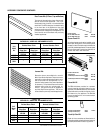
Figure 8
FRONT OF FIREPLACE
REAR BURNER
FRONT BURNER
Outer Log
Notch Location
FIREBOX SUBFLOOR
Outer Log
Notch Location
Outer Log
Notch Location
Outer Log
Notch Location
Riser - Inner Log
Notch Location
LOG NOTCH LOCATION RELATIVE TO BURNER
Pilot Assembly
Riser - Inner Log
Notch Location
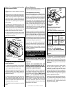
NOTE: INSTALL REAR BURNER FIRST,
THEN FRONT BURNER.
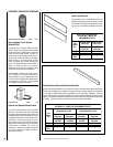
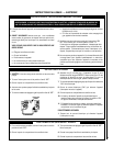
BURNER POSITIONING
REAR BURNER
FRONT BURNER
PILOT
BURNER
Note: The burners are not identical. Position them so
that the circular burner ports run as shown. Note
especially the vertical run of ports relative to the pilot
burner. Bracket A on the rear burner will interfere
with the pilot burner if an attempt is made to install
the rear burner in the front burner’s position.
BRACKET A
BURNER
PORTS
NOTE: INSTALL REAR BURNER FIRST,
THEN FRONT BURNER.
MILLIVOLT
Thermocouple
Hood
Ignitor Rod
³⁄₈" Min
(9 mm)
Thermopile
Pilot
Nozzels
WARNING: THIS APPLIANCE IS NOT
DESIGNED TO BURN WOOD. ANY AT-
TEMPT TO DO SO COULD CAUSE IR-
REPARABLE DAMAGE TO YOUR APPLI-
ANCE AND PROVE HAZARDOUS TO
YOUR SAFETY.
WARNING: THE SIZE AND POSITION
OF THE LOG SET WAS ENGINEERED TO
GIVE YOUR APPLIANCE A SAFE, RELI-
ABLE AND ATTRACTIVE FLAME PAT-
TERN. ANY ATTEMPT TO USE A DIF-
FERENT LOG SET IN THE FIREPLACE
WILL VOID THE WARRANTY AND WILL
RESULT IN INCOMPLETE COMBUS-
TION, SOOTING, AND POOR FLAME
QUALITY.
WARNING: LOG SET GETS VERY HOT
AND WILL REMAIN HOT UP TO ONE
HOUR AFTER GAS SUPPLY IS TURNED
OFF. HANDLE ONLY WHEN LOG SET IS
COOL. TURN OFF ALL GAS TO THE
APPLIANCE BEFORE INSTALLING THE
GRATE AND LOG SET.