


NOTE: DIAGRAMS & ILLUSTRATION NOT TO SCALE.
12
The appliances covered in this manual are
heater rated and produce a great deal of heat.
Decorative brass trim pieces and hoods may
tarnish because of their proximity to the heater
opening and front face. Tarnishing of these
pieces is normal, unavoidable and should be
expected.
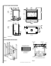
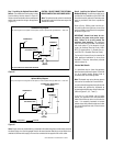
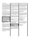
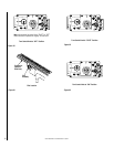
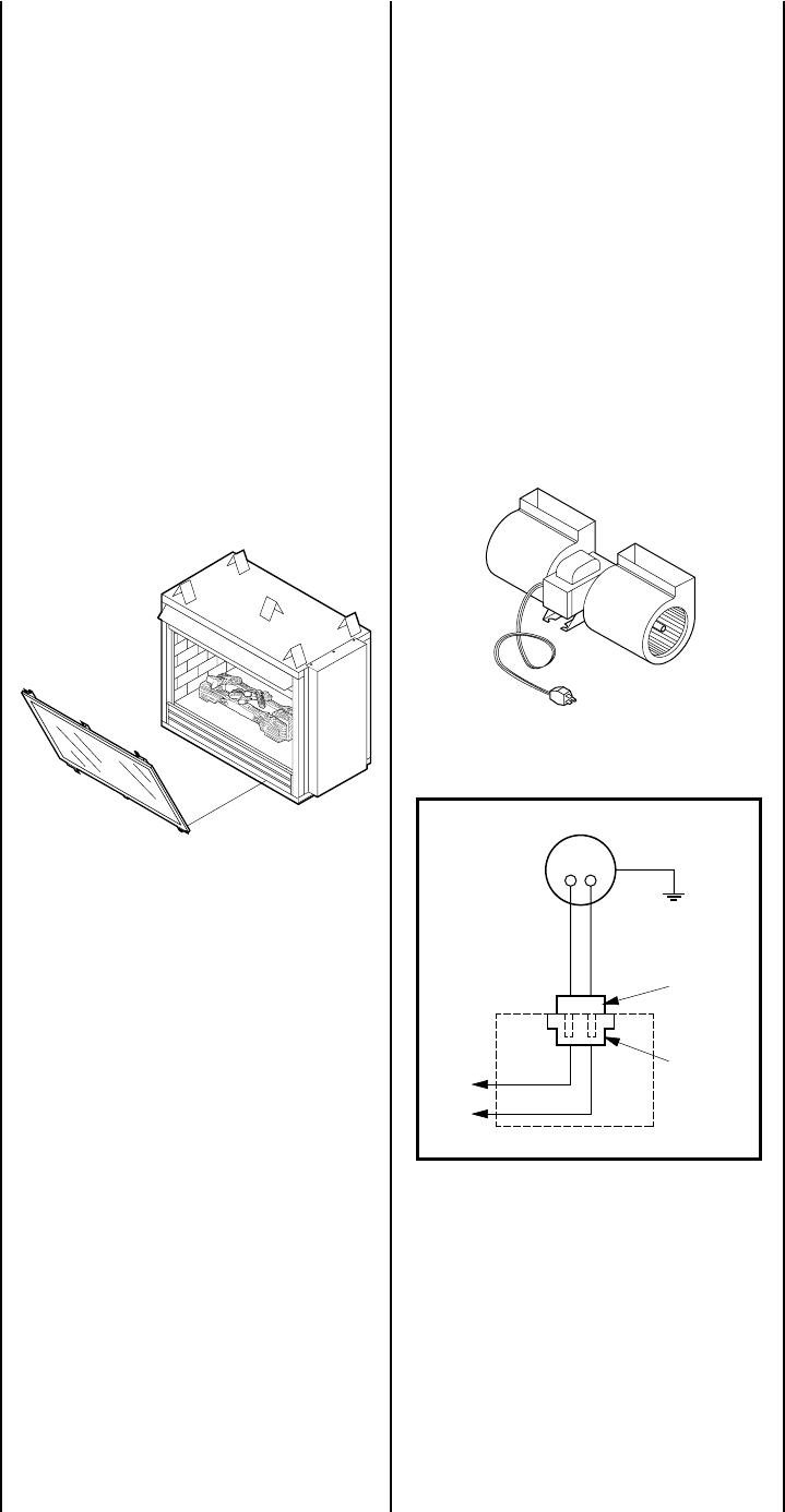
Forced Air Kit
The FAB-1100 assembly provides a forced air
circulation feature for your appliance. This kit
mounts directly into the lower intake chamber
with an electrical connection made at the re-
ceptacle provided. The appliance must have an
independent 120Vac power line incorporated
at the time of installation. Refer to Step 6 of the
installation instructions supplied with the
forced air kit (
Figures 21 and 22
).
Figure 21
Remote Control Kit
The Model RCK adds the convenience of re-
mote control for your appliance. The kit in-
cludes a wireless, hand held transmitter and a
receiver that replaces the wall switch. This
special receiver permits either manual or re-
mote control modes. Both receiver and trans-
mitter operate on standard 9 volt batteries (not
included). Refer to the RCK installation instruc-
tion for specific details.
Wall Switch Kit
An optional wall switch kit can be installed
along with all vent-free appliances. The kit
consists of a standard UL wall switch with
cover plate. This kit provides for remote (wall)
operation of the appliance. Replace the wall
switch and cover plate of this kit with the
components of the RCK and you can have true
remote control of your vent-free appliance,
turning it on and off from your favorite easy
chair. The wall switch kit should be installed
along with the appliance. Refer to
Figure 13
and Step 6 for detailed installation instructions.
Optional on Unit Rocker Switch
An optional rocker switch kit can be installed
directly on all CFST and CFPF series appliances
to provide for On and Off operation in lieu of a
wall switch. This kit is designed to install in the
lower control compartment out of view and is
perfect for use in high volume areas such as
lobbies and model homes where limited access
to the appliance On/Off switch is desirable. This
kit can be retrofitted to previously installed
appliances and may be temporarily installed in
place of other switch circuitry.
Decorative Volcanic Stone
The decorative volcanic stone, Model DVS,
can be used to enhance the look of your
appliance. Spread the decorative volcanic stone
evenly around the bottom of the firebox.
Screen Panel Kit
An optional screen panel can be installed on the
CFST door. This screen panel is easy to install
using the provided hardware. This kit can be
retrofitted to previously installed CFST appli-
ances. The screen panel kit may not be used in
conjunction with either of the decorative arches.
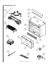
Grounded
to Appliance
Blower Motor
Motor Plug
Receptacle
120V
Appliance Junction Box
Figure 22
To light the burner; turn “ON” the optional
remote wall switch (if installed) and rotate the
gas valve control knob counterclockwise to
the “ON” position.
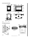
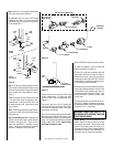
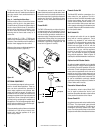
Step 11. Installing the Glass Door –
Position the door frame in front of the firebox
opening, with the joint in the gasket down.
Locate the three (3) tabs at the bottom edge of
the door frame into the three (3) brackets at
the base of the fireplace front opening. Lean
the door frame back towards the fireplace
ensuring that the frame seats evenly as it
draws shut.
Install the three (3) ¹⁄₄"-20 x 1" Phillips pan
head screws removed previously and tighten
to secure. Ensure that the tab on the bottom of
the door frame engages the door switch.
Make sure the screws are tightened equally to
avoid torquing the door (
Figure 20
).
Figure 20
OPTIONAL EQUIPMENT
An incomparable package of options are avail-
able for use with these appliances. These op-
tions can both customize the operation of
these unique appliances and enhance their
beauty and charming appeal. All options are
available in kit form, are easy to install and are
packaged complete with all required parts and
instructions. Some of the option kits need to
be fitted prior to completing the installation of
the appliance. The following paragraphs detail
the kit options available for use with the appli-
ances covered in this manual.
These outstanding optional items can be added
individually or in sets of two or more to cus-
tomize your vent-free appliance to fit your
homes unique needs.