


356214-XIM-A-0108
44 Johnson Controls Unitary Products
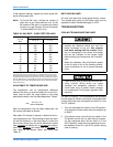
MANIFOLD GAS PRESSURE ADJUSTMENT
Small adjustments to the high-fire gas flow may be
made by turning the pressure regulator adjusting screw
on the automatic gas valve.
Adjust as follows:
1. Remove the cap on the regulator. It's located next
to the push-on electrical terminals.
2. To decrease the gas pressure, turn the adjusting
screw counterclockwise.
3. To increase the gas pressure, turn the adjusting
screw clockwise.
NOTE: The correct manifold pressure for these fur-
naces is 3.65 IWG ±0.3.
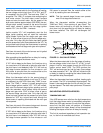
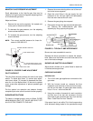
PILOT CHECKOUT
The pilot flame should envelope the end of the flame
sensor. To adjust pilot flame, (1) remove pilot adjust-
ment cover screw, (2) increase or decrease the clear-
ance for air to the desired level, (3) be sure to replace
cover screw after adjustment to prevent possible gas
leakage.
Put the system into operation and observe through
complete cycle to be sure all controls function properly.
BURNER INSTRUCTIONS
To check or change burners, pilot or orifices, CLOSE
MAIN MANUAL SHUT-OFF VALVE AND SHUT OFF
ALL ELECTRIC POWER TO THE UNIT.
1. Remove the screws holding either end of the mani-
fold to the burner supports.
2. Open the union fitting in the gas supply line just
upstream of the unit gas valve and downstream
from the main manual shut-off valve.
3. Remove the gas piping closure panel.
4. Disconnect wiring to the gas valves and spark ignit-
ors. Remove the manifold-burner gas valve
assembly by lifting up and pulling back.
Burners are now accessible for service.
Reverse the above procedure to replace the assem-
blies. Make sure that burners are level and seat at the
rear of the heat exchanger.
BURNER AIR SHUTTER ADJUSTMENT
Adjust burner shutters so no yellow flame is observed
in the heat exchanger tubes.
CHECKING GAS INPUT
NATURAL GAS
1. Turn off all other gas appliances connected to the
gas meter.
2. With the furnace turned on, measure the time
needed for one revolution of the hand on the small-
est dial on the meter. A typical gas meter usually
has a 1/2 or a 1 cubic foot test dial.
3. Using the number of seconds for each revolution
and the size of the test dial increment, find the
cubic feet of gas consumed per hour from the Gas
Rate - Cubic Feet Per Hour Table 23.
If the actual input is not within 5% of the furnace rating
(with allowance being made for the permissible range
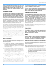
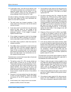
FIGURE 22 - PROPER FLAME ADJUSTMENT
1 / 8 " G A P B E T W E E N C A R R Y - O V E R
T U B E A N D F L A M E S E N S O R B U L B
C A R R Y - O V E R T U B E
F L A M E S E N S O R B U L B
B U R N E R A S S E M B L
Y B R A C K E T
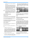
FIGURE 23 - TYPICAL FLAME APPEARANCE