


13
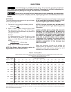
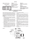
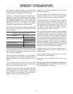
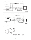
Minimum Clearances for
Termination Locations
Structure
Vent Systems
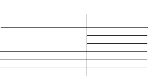
Termination Clearance Requirements
Door, window or any gravity vent inlet
Forced air inlet within 10 ft.
Adjoining building or parapet
Adjacent public walkways
4 feet below
4 feet horizontally
1 foot above
3 feet above
6 feet
7 feet above grade
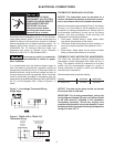
HORIZONTALLY VENTED UNIT HEATERS
(CATEGORY I - U.S. RESIDENTIAL ONLY)
All venting of residential tubular unit heaters must
comply with CSA International Requirement 10.96 U.S.
for Unit Heaters for Residential Use (2
nd
Edition).
Category I horizontal venting arrangements are
designed to be used with either single wall vent pipe or
double wall (Type B) vent pipe. These arrangements
must terminate external to the building using either
single wall or double wall (Type B) vent. See Table 4
and Figures 13 and 14 for special installation
requirements regarding these venting conditions.
An Amerivent Americap, Fields Starkap, or Metalbestos
vent cap must be supplied by the customer for each
power vented unit.
The venting system for these appliances shall terminate
at least 4 feet (1.2m) below, 4 feet (1.2m) horizontal
from, or 1 foot (0.3m) above any door, window, or gravity
vent air inlet into the building.
The vent terminal must be at least 12 inches (305mm)
from the exterior of the wall that it passes through to
prevent degradation of the building material by flue
gases.
The vent terminal must be at least 3 feet (1m) above
grade, or in snow areas, at least 3 feet (1m) above the
snow line to prevent blockage by snow.
Through the wall vent for these appliances shall NOT
terminate over public walkways, or over an area where
the condensate or vapor could create a nuisance or
hazard or could be detrimental to the operation of
regulators, relief valves, or other equipment.
Maintain 1 inch (25.4mm) between the vent pipe and
combustible materials.
The vent terminal must be installed with a minimum
horizontal clearance of 4 feet (1.2m) from electric
meters, gas meters, regulators, and relief equipment.
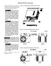
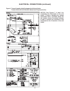
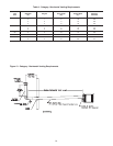
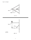
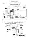
The horizontal portion of the vent pipe must not exceed
8 feet (2.44m) for the 30 unit size or 10 feet (3.05m) for
the 45 to 90 unit sizes. The minimum length for the
horizontal portion of the vent pipe is 4 feet (1.22m). The
vent system must be constructed as shown in Table 4
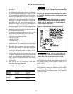
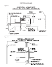
and Figure 13. The vent pipe and vertical extension
must be supported as shown in Figure 14.
Seal all vent pipe joints and seams to prevent leakage.
Use General Electric RTV-108, Dow-Corning RTV-732,
or equivalent silicone sealant with a temperature rating
of 500°F, or 3M #425 aluminum foil tape (or equivalent).
The vent system must be installed to prevent collection
of condensate. Pitch horizontal pipes downward 1/4 inch
per foot (21mm per meter) toward the outlet for
condensate drainage. Install a tee with a condensate
drain at the low point of the pipe (See Figure 13). As an
alternate, a 3/8 inch diameter hole may be drilled at the
low point of the pipe for condensate drainage.
Horizontal portions of the venting systems shall be
supported at maximum intervals of 4 feet (1.2m) to
prevent sagging.
Insulate single wall vent pipe exposed to cold air or
running through unheated areas.
Local codes may supersede any of the above
provisions.
Each unit must have an individual vent pipe and
vent terminal! Each unit MUST NOT be connected to
other vent systems or to a chimney.