


37
Line voltage power can
cause product damage,
severe injury or death.
Only a trained experienced
service technician should
perform this trouble-
shooting.
1. Check the system thermo-
stat to make sure it is call-
ing for heat. (Do not cycle
the thermostat on and off at
this time.)
2. Remove the access panel.
Do not interrupt power to
the control board by opening
any electrically interlocked
panels.
3. Observe the LED indicator
on the control board (a
green LED labeled “OK”
indicates system faults);
check and repair system
as noted in the chart to the
right.
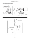
*NOTICE: Air flow proving
switch and power venter
hose barbs must be free
of any dust or debris at all
times. Periodically check
these openings and/or if any
problems occur.
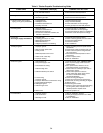
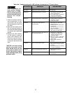
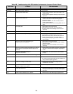
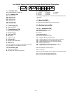
Table 10A - Troubleshooting with LED Indicator Assistance for UT Control Board
Not Applicable
Not Applicable
1. Line voltage on terminals 120
and C on transformer.
2. Low voltage (24V) on terminals
24 and C on transformer.
3. 5 Amp fuse on circuit board.
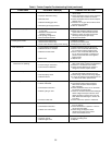
1. Common side of transformer
grounded to chassis.
2. Loose spark ignitor.
1. Gas supply off or gas supply
pressure too low.
2. Flame sense rod contaminated
or loose wire.
3. Gas valve switch is off or wires
are not connected.
4. Broken or cracked porcelain on
fl ame probe or spark ignitor.
1. Obstructions or restrictions
in appliance air intake or fl ue
outlet are preventing proper
combustion airfl ow.
2. Moisture or debris in tubing that
connects pressure switch and
draft inducer.
3. Airfl ow switch jumpered or
miswired.
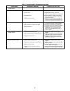
1. Open manual reset rollout switch.
2. Gas pressure too high, over fi re
condition.
3. Incorrect airfl ow due to blockage
or motor not operating.
1. Flame probe miswired or
shortened.
1. Thermostat is interfering with
control board.
Control OK, no call for heat.
Control OK, call for heat present.
Internal control fault, or no power.
Control internal failure or bad ground.
In lockout from failed ignitions
or fl ame losses.
Pressure Switch open with inducer on
or closed with inducer off.
Limit or rollout switch is open.
Flame sensed while gas valve is off.
On-board microprocessors disagree.
LED STATUS
INDICATES CHECK/REPAIR
Slow Flash
Fast Flash
Steady Off
Steady On
2 Flashes
3 Flashes
4 Flashes
5 Flashes
6 Flashes