


30
VENTING (continued)
AIR INLET COLLAR
Remove screen and mounting plate from air inlet on
rear panel of unit by removing 4 screws. Secure inlet
collar and gasket to inlet opening re-using the 4 screws
removed in step one.
EXHAUST AIR COLLAR
Secure 5-4” reducer to flue collar on rear panel of
unit sizes 090, 105 and 120. Seal per exhaust venting
instructions.
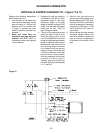
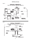
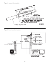
VERTICAL TERMINATION
Select location on roof for vent terminal, ensuring
adequate space inside the building/structure for
concentric vent box. Terminal must be at least 6 feet
(1.8m) from any wall or adjoining building. See Figure
22.
Cut a hole through the roof for combustion air pipe.
Concentric vent box is to be suspended from the
underside of the roof using suitable brackets (field
supplied). Before mounting box, cut a length of 6 inch
(152mm) (sizes 030-075) or 8 inch (203mm) (sizes
090-120) pipe so that dimension A, Figure 22, is equal
to the dimension from the top of the box to the roof
surface plus 20 inches or plus maximum expected
snow depth, whichever is greater. Fasten pipe to
combustion air inlet connection of concentric vent box
and seal joint. Insert pipe through roof and fasten vent
box in place. Flash and/or caulk pipe to roof. Install inlet
air screen assembly and fasten to pipe with screws.
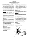
Insert a 5 foot length of Type B vent pipe through the
concentric vent box opening (detail A, Figure 20) with
the "UP" arrow pointing up. Position the pipe to extend
12 inches beyond the inlet air screen. Secure the Type
B vent pipe in position by drilling three small equally
spaced holes through the collar of the concentric vent
box and inserting sheet metal screws. Install defl ector
disk on Type B vent pipe 2-1/2 inches above inlet air
screen and fasten with screws. Seal joint between
defl ector disk and pipe with silicone sealant. Install vent
terminal on top of Type B vent pipe, fasten with screws
and seal joint.
Connect flue pipe and combustion air pipe from
concentric vent box to unit, following instructions on
pages 26 and 27. Joint between Type B vent pipe
and single wall vent pipe must be sealed with high
temperature silicone sealant. (See Figure 21) Collars
on unit and on concentric vent box are sized so that
crimped ends of combustion air pipes go toward the
unit and crimped ends of flue pipes go away from the
unit.
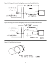
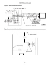
HORIZONTAL TERMINATION
Select a location on outside wall for vent terminal. In
most applications, the terminal should be on level with
the fl ue outlet of the unit less a 1/4 inch per foot pitch
for condensate drainage toward the outside of the
building. See Figure 23.
The location of the vent terminal must be in accordance
with the National Fuel Gas Code ANSI Z223.1 in the U.S.
or the Natural Gas Installation Code CAN/CGA-B149.1
or the Propane Gas Installation Code CAN/CGA-149.2
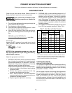
in Canada. See Table 4 for minimum clearances. In
Canada, a vent shall not terminate above a meter/
regulator assembly within 3 feet (.9m) horizontally of
the vertical centerline of the regulator nor within 6 feet
(1.8m) of any gas service regulator vent outlet.
Cut a hole through the wall for a 6 inch (152mm) sizes
(030-075) or 8 inch (203mm) sizes (090-120) combustion
air pipe. Install thimble if required by local codes or
type of wall construction. Concentric vent box may be
fastened directly to wall or spaced away from wall using
suitable brackets (fi eld supplied). Cut a length of pipe so
that it will protrude 4 inches (102mm) through the wall
when the box is mounted in position. Fasten pipe to box
with sheet metal screws, using at least three screws per
joint. Seal joint with silicone sealant. Insert pipe through
wall and fasten adapter box in place so that the pipe
pitches downward 1/4 inch per foot (21mm/m) toward
the outside. Flash and/or caulk pipe on outside wall.
Install inlet air screen assembly and fasten to pipe with
screws. Insert a 3 foot length of 4 inch (sizes 030-075)
or 5 inch (sizes 090-120) Type B vent pipe through the
concentric vent box opening (detail A, Figure 20) with
the "UP" arrow pointing toward the outside. Position the
pipe to extend 12 inches beyond the inlet air screen.
Secure the Type B vent pipe in position by drilling three
small equally spaced holes through the collar of the
concentric vent box and inserting sheet metal screws.
Install defl ector disk on Type B vent pipe 2-1/2 inches
(63.5mm) from inlet air screen and fasten with screws.
Install vent terminal on end of Type B vent pipe, fasten
with screws and seal joint.
Connect fl ue pipe and combustion air pipe from concentric
vent box to unit, following instructions on pages 26
and 27. Joint between Type B vent pipe and single
wall vent pipe must be sealed with high temperature
silicone sealant. (See Figure 21) Collars on unit and on
concentric vent box are sized so that crimped ends of
combustion air pipes go toward the unit and crimped
ends of fl ue pipes go away from the unit.
SEPARATED COMBUSTION