


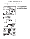
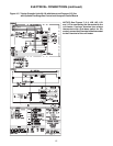
9
Do not over tighten the inlet gas
piping into the valve. This may cause stresses that
will crack the valve!
NOTICE: Use pipe joint sealant resistant to the
action of liquefied petroleum gases regardless of
gas conducted.
Check all pipe joints for leakage
using a soap solution or other approved method.
Never use an open flame or severe personal
injury or death may occur!
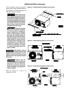
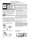
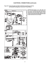
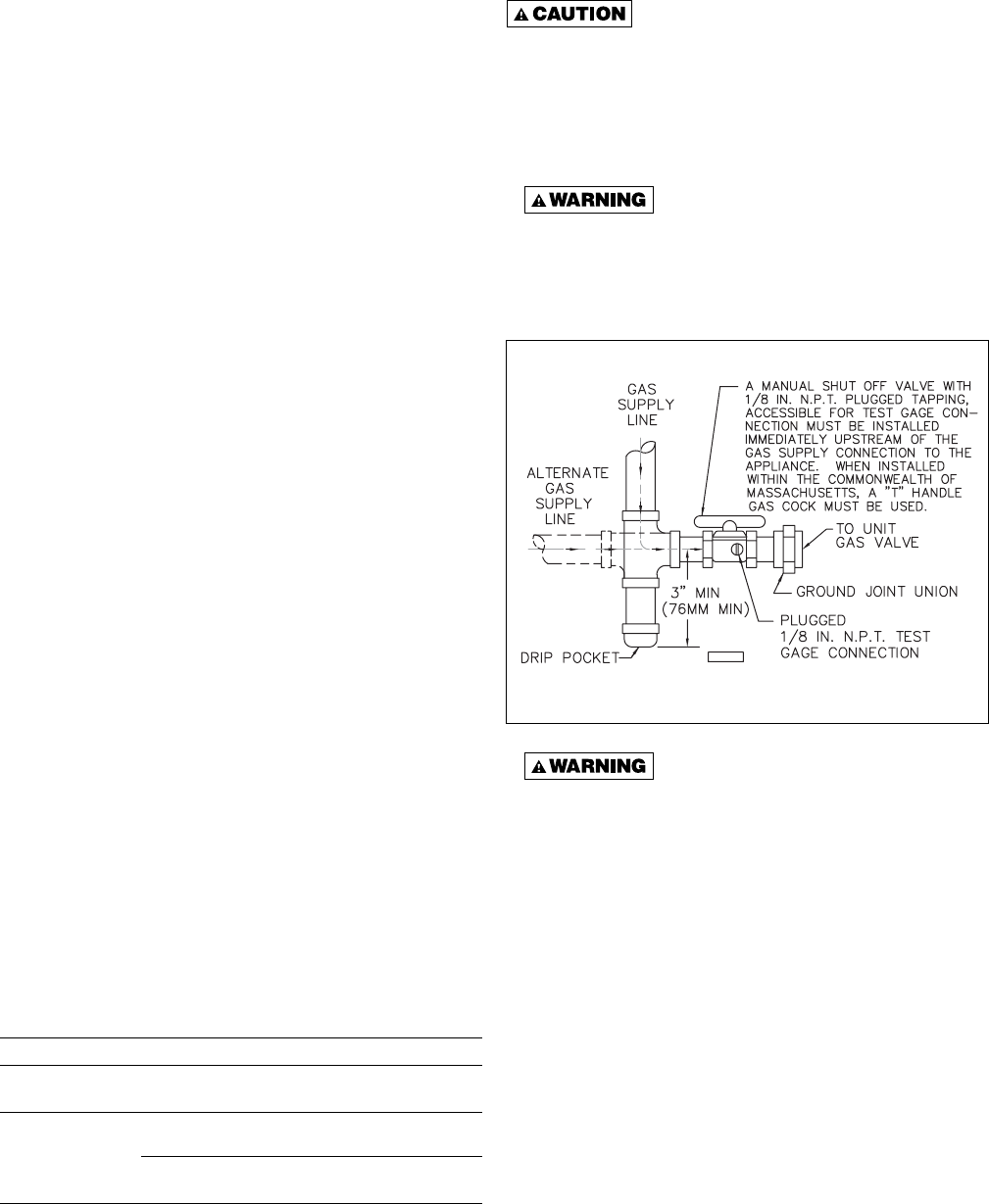
Figure 6 - Pipe Installation, Standard Controls
Never use an open fl ame to detect
gas leaks. Explosive conditions may exist which
may result in personal injury or death!
The appliance and its individual shutoff valve must be
disconnected from the gas supply piping system during
any pressure testing of that system in excess of 1/2 psig
(3.5 kPa).
The appliance must be isolated from the gas supply
piping system by closing its individual manual shutoff
valve during any pressure testing of the gas supply
piping system at test pressures equal to or less than
1/2 psig (3.5 kPa).
PIPE INSTALLATION
1. Install the gas piping in accordance with applicable
local codes.
2. Check gas supply pressure. Each unit heater must
be connected to a gas supply capable of supplying
its full rated capacity as specifi ed in Table 3. A fi eld
LP tank regulator must be used to limit the supply
pressure to a maximum of 14 in. W.C. (3.5 kPa).
All piping should be sized in accordance with the
latest edition of ANSI Standard Z223.1 National
Fuel Gas Code; in Canada, according to CGA-B149.
See Tables 1 & 2 for correct gas piping size, and
also refer to Tables 3, 7 and 8. If gas pressure is
excessive on natural gas applications, install a
pressure regulating valve in the line upstream from
the main shutoff valve.
3. Adequately support the piping to prevent strain on
the gas manifold and controls.
4. To prevent the mixing of moisture with gas, run the
take-off piping from the top, or side, of the main.
5. Standard Unit Heaters are supplied with a
combination valve which includes:
a. Manual "A" valve
b. Manual "B" valve
c. Solenoid valve
d. Pressure regulator
Pipe directly into the combination valve (see Figure
6).
6. Gas valve has a pressure test post requiring a
3/32" hex head wrench to read gas supply and
manifold pressures. Open 1/4 turn counterclockwise
to read, turn clockwise to close and reseat. A 5/16"
ID hose fi ts the pressure post.
7. Provide a drip leg in the gas piping near the gas
unit heater. A ground joint union and a manual gas
shutoff valve should be installed ahead of the unit
heater controls to permit servicing. The manual
shutoff valve must be located external to the jacket.
(See Figure 6)
8. Make certain that all connections have been
adequately doped and tightened.
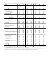
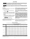
Table 3 - Gas Piping Requirements
GAS PIPING REQUIREMENTS*
GasType Natural Gas Propane (LP) Gas
Manifold 3.5 in. W.C. 10.0 in. W.C.
Pressure (0.9 kPa) (2.5 kPa)
14.0 in. W.C. Max. 14.0 in. W.C. Max.
Supply Inlet (3.5 kPa) (3.5 kPa)
Pressure
5.0 in. W.C. Min. 11.0 in W.C. Min.
(1.2 kPa) (2.7 kPa)
*For single stage application only at altitudes below 2,001 feet.
D3631C