


Page 34 of 53
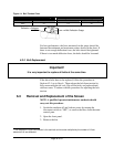
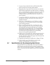
Figure 14: Belt Tension Chart
Belt Cross Section Small O.D. Range
∗
∗∗
∗Deflection Force Lbs/V-belt
Run-In Normal Running
3VX 3.7 7.0 4.7
For best performance, the force measured on the gauge should be
between the minimum and maximum values shown on the chart. If
there is not enough deflection force, the belts should be tightened.
If there is too much deflection force, the belts should be loosened.
6-2-3 Belt Replacement
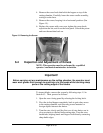
Important!
It is very important to replace all belts at the same time.
If the drive belts have to be replaced, follow the procedure in
Section 6-2-1 up to Step 6. Then release the belt from tension by
fully unscrewing the tie rods. Slip off the belts, and replace them
with new ones. Continue with the procedure for adjusting the belt
tension.
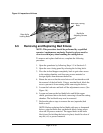
6-3 Removal and Replacement of the Screen
NOTE: A qualified operator/maintenance mechanic should
carry out this procedure.
1. Switch the machine off and lockout power by turning the
disconnect switch to “OFF”, or remove the fuses from the main
control pane.
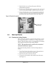
2. Open the front panel.
3. Remove the bin.
∗ The Deflection Force Value shown is for each belt and must be multiplied by the number of V-belt
elements if all are deflected.
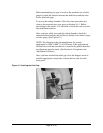
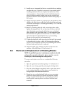
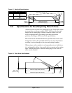
Belt Span
Deflection = Beltspan
64
Belt Deflection Guage