


Fiberglass Cooling Towers Chapter 3: Installation Page 11 of 25
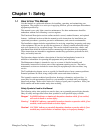
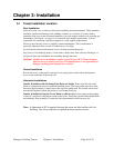
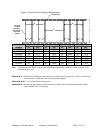
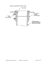
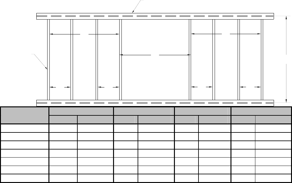
Figure 1: Structural Steel Support Requirements
TSE50
Structural steel
A
C
C
B
B
C
C
D
2 X 2 angle
to support
tower basin,
flush with top
of structural
steel rails
Model A B C D
number in. cm in. cm in. cm in. cm
SF2003 52 132.1 50 127.0 16 40.6 78 175.3
SF2004 52 132.1 50 127.0 16 40.6 78 175.3
SF2005 68 172.7 67 170.2 22 55.9 78 175.3
SF2007 68 172.7 67 170.2 22 55.9 78 175.3
SF2009 87 221.0 85 215.9 28 71.1 78 175.3
SF2011 87 221.0 85 215.9 28 71.1 78 175.3
SF2015 87 221.0 85 215.9 28 71.1 78 175.3
Note: The illustration in Figure 1 shows structural steel with spacing for two (2) cooling towers. Your
installation may vary.
Dimension A – Centerline for fiberglass mounting feet provided with cooling tower. This is so bolt holes
can be made to secure the tower to the structural support.
Dimension B & C – Location of basin support steel.
Dimension D – Provides proper distance of 60” between cooling towers and distance between cooling
tower and the wall of a building.