


Cabinet Series Dehumidifying Dryer 51
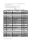
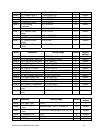
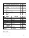
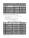
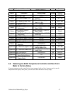
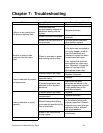
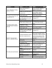
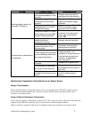
Problem Possible cause Corrective action
The internal mechanism is
not inserted properly into the
housing.
Properly insert the internal
mechanism into the housing.
The power supply is not
connected to its terminals
properly.
Properly connect the power
supply to the power supply
terminals.
No power is supplied, or the
supplied power is not within
the specified range.
Supply a voltage of 85 to 125
VAC to the power supply
terminals of the controller.
Nothing displays when the
controller is turned on.
Disconnect switch or Control
Power switch not set to ON.
Control Power fuse blown.
Check control power fuse for
continuity. Turn disconnect
switch and control power
switch ON.
Input polarity on thermo-
couple is wrong or
connection is wrong.
Properly wire the terminals.
No compensating lead wires
used for extension of the
thermocouple.
Use proper compensating
lead wires and terminals.
Thermocouple and controller
are connected by wires other
than proper lead wires.
Use a dedicated thermo-
couple connector. If a
connector is a metal different
from the thermocouple and
controller, a temperature
error may result.
Sensor is broken or short-
circuited.
Replace with a good sensor.
The controller is influenced
by noise or other induction.
Separate input wires as far
as possible from the origin of
the noise.
Process value is abnormal or
not obtained.
Celsius temperatures used
instead of Fahrenheit or vice
versa.
Setup mode level 2 display
d-U. S-V display shows
setting.
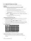
Determining Temperature Controller Errors or Sensor Errors
Using a Thermocouple
If the controller displays a temperature that is close to room temperature (70ºF/21ºC) when you short-
circuit controller input terminals, the controller is normal and the sensor is probably broken, short-
circuited, or incorrectly wired.
Using a Platinum Resistance Thermometer
If the controller displays a temperature of about 0.0°C (32ºF) when you insert a 100-ohm resistor between
terminals A and –B of the controller, and you short-circuit controller terminals +B and
–B, the controller is normal and the sensor is probably broken, short-circuited, or incorrectly wired.