


ULTRAFORCE COMMERCIAL GAS WATER HEATER
SUF 120 thru 400 SERVICE HANDBOOK
State Water Heaters – Technical Training Department 27 Ashland City, Tennessee © 2009
Servicing should only be performed by a Qualified Service Agent 198152-002
CONTROLS – PRESSURE SWITCHES – ALL MODELS
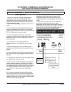
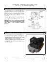
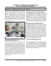
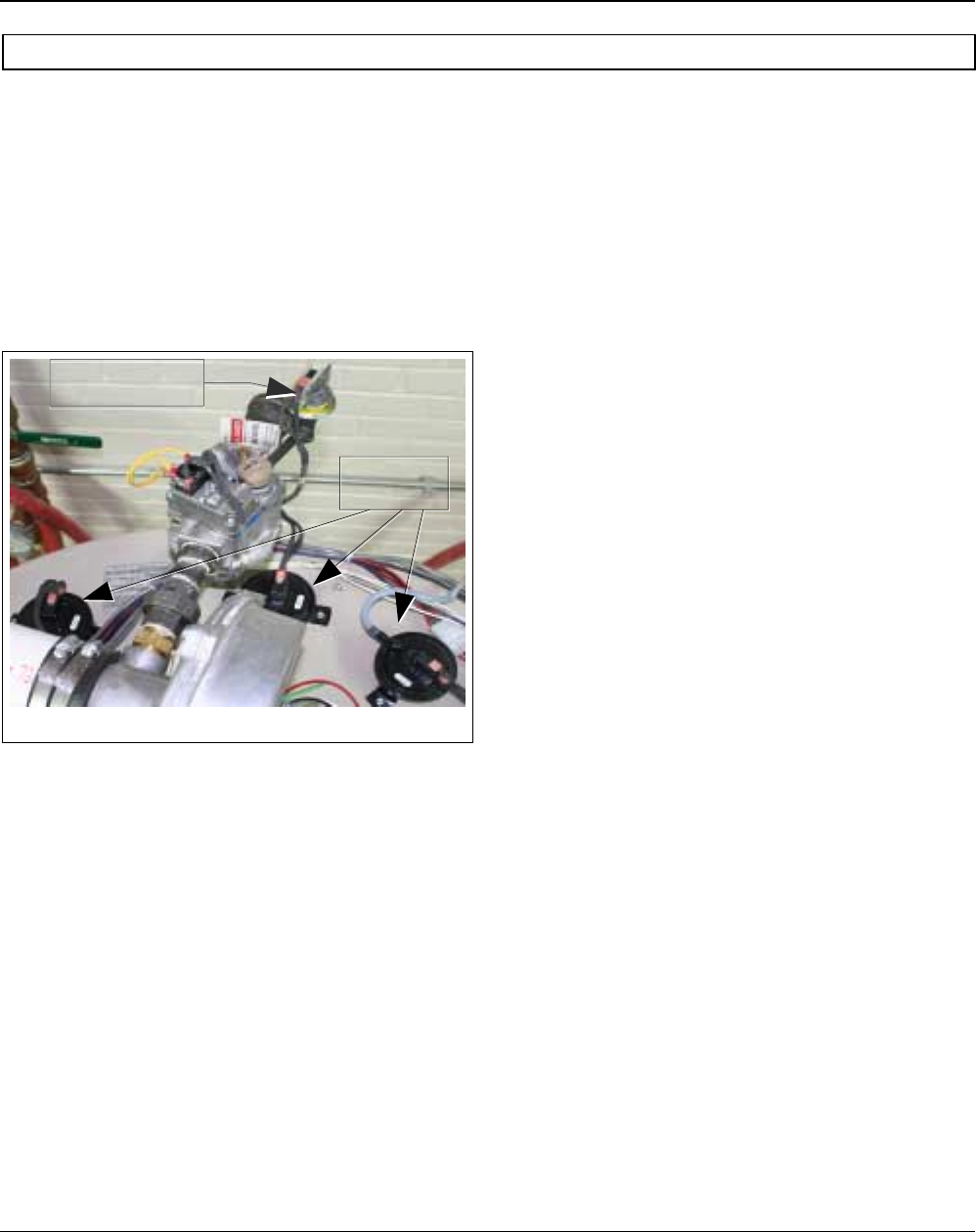
All SUF models are provided with four pressure
switches. These switches are essential to the
safe an d pr oper op eration o f the uni t. T he
switches are wired to the central control board
(CCB) individually an d ea ch i s monitored
individually. The (CCB) is set up to shut the unit
down whenever there is a failure of any of the
switches and declare a fault for each individual
switch. It is important to understand the purpose
of each switch.
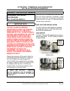
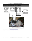
BLOWER PROVING SWITCH
The Blower Proving S witch i s pr ovided on t he
heater to v erify that the fan is op erating. It i s a
positive pressure switch whose electrical contacts
are normally open. The blower p roving switch
electrical contacts will close on a rise in pressure
as the blower increases the pressure in the burner.
This switch is connected to the burner tap b y a
piece of Tygon (soft plastic) tubing. This tubing
must be connected in order for the switch to close
the electrical contacts. The controller requires that
the electrical contacts on this pressure switch be
open before it will allow the blower to come on. The
control w ill declare a f ault on the U IM if ei ther
condition occurs.
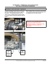
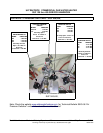
BLOCKED OUTLET PROVING SWITCH
The blocked outlet proving switch electrical contacts
are normally closed. The blocked outlet proving
switch electrical contacts w ill open on a rise in
pressure. Check t o see i f t he c ondensate i s
allowed to flow freely from the exhaust elbow and
for obstructions in the exhaust venting and exhaust
vent terminal. Also check the t hat the equivalent
feet of vent pipe for the specific model has not been
exceeded. Check the vent length tables on page 9
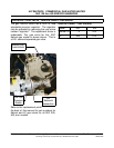
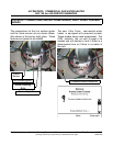
BLOCKED INLET PROVING SWITCH
The Blocked Inlet Proving switch electrical contacts
are normally closed. The bl ocked inlet pr oving
switch el ectrical c ontacts w ill op en when an
increase in negative pressure (vacuum) occurs
in the intake vent pipe. The switch is connected to
the pressure tap on the PVC flange connected to
the inlet of the blower. When this switch prevents
the u nit f rom ig niting, most li kely the in take is
blocked by some means. Verify that the air intake
pipe and ai r i ntake v ent t erminal ar e f ree of
obstructions that may prevent air from entering the
unit. Also check the that the equivalent feet of vent
pipe for the specific model has not been exceeded.
Check the vent length tables on page 9
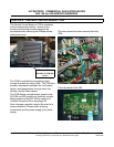
LOW GAS PRESSURE SWITCH
The Low Gas Pressure Switch electrical contacts
are normally open. The low gas pressure switch
electrical contacts will close on a rise pressure.
The c ontacts w ill open w hen t he p ressure falls
below the fixed set point. If this happens during a
heating cycle a the burner will be shut down and a
fault will be declared on the UIM.
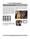
Low Gas Pressure
Switch
Pressure
Switches