


RESIDENTIAL GAS, NON POWER VENTED, WATER HEATER
SERVICE HANDBOOK
State Water Heater Technical Training Department
© 2004 Ashland city, TN
20
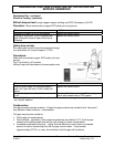
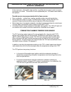
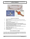
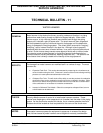
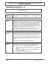
To replace a pilot assembly:
1. Turn off the gas supply
2. Disconnect the piezo cable from the piezo button (connection near gas control
valve).
3. Disconnect the pilot tubing, thermocouple and main burner tube from the bottom of
the gas control valve.
4. Remove (2) 3/8 inch nuts securing the inner door.
5. Remove the entire burner assembly.
6. Remove screw securing pilot burner assembly to pilot mounting bracket.
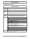
7. Remove pilot assembly - with orange gasket – from the back side of the inner door.
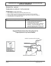
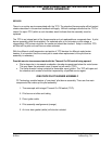
8. Reinsert new pilot assembly into back side of inner door. Wetting the orange gasket
may help in securing the gasket into place.
9. Reattach the new pilot assembly to the pilot mounting bracket.
10. Inspect/replace the white, inner door gasket before making the connections to the
bottom of the gas control valve.
11. Reattach the piezo cable to the piezo button.
12. Remount the inner door.
13. Follow the pilot lighting instructions including gas and gasket leak checks.
14. Install the outer door.
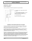
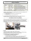
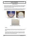
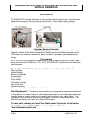
SEALED COMBUSTION CHAMBER
The combustion chamber is factory sealed around the flame arrestor and the upper and lower
perimeter of the chamber. Access for service is provided through an inner door as with current
product. However, this inner door is now sealed with; a door gasket, a pilot assembly grommet
type seal, and a main burner tube boot/sleeve type seal.