


7
any direction. If the heater is installed in a carpeted alcove, the
entire floor shall be covered by the panel. Also, see the DRAINING
requirements in MAINTENANCE Section.
THE HEATER SHALL BE LOCATED OR PROTECTED SO IT IS
NOT SUBJECT TO PHYSICAL DAMAGE BY A MOVING VEHICLE.
WARNING
FLAMMABLE ITEMS, PRESSURIZED CONTAINERS OR ANY
OTHER POTENTIAL FIRE HAZARDOUS ARTICLES MUST
NEVER BE PLACED ON OR ADJACENT TO THE HEATER. OPEN
CONTAINERS OR FLAMMABLE MATERIAL SHOULD NOT BE
STORED OR USED IN THE SAME ROOM WITH THE HEATER.
THE HEATER MUST NOT BE LOCATED IN AN AREA WHERE IT
WILL BE SUBJECT TO FREEZING.
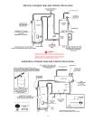
LOCATE IT NEAR A FLOOR DRAIN. THE HEATER SHOULD BE
LOCATED IN AN AREA WHERE LEAKAGE FROM THE
HEATER OR CONNECTIONS WILL NOT RESULT IN DAMAGE
TO THE ADJACENT AREA OR TO LOWER FLOORS OF THE
STRUCTURE.
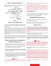
WHEN SUCH LOCATIONS CANNOT BE AVOIDED, A SUITABLE
DRAIN PAN SHOULD BE INSTALLED UNDER THE HEATER.
Such pans should be fabricated with sides at least 2" (50.8 mm)
deep, with length and width at least 2" (50.8 mm) greater than
the diameter of the heater and must be piped to an adequate
drain. The pan must not restrict combustion air flow.
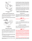
LEVELING
If the unit is not level, insert the bolts which were used in crating
into the legs to correct this condition.
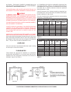
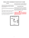
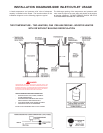
CLEARANCES
These heaters are approved for installation on combustible
flooring (with Leg Kit #6570-7) in an alcove when the minimum
clearance from any combustion construction are followed as
indicated in figure 6 and Table 4.
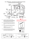
In all installations the minimum combustible clearances from
vent piping shall be 6" (152mm). Vent piping passing through a
combustible wall or ceiling must be a continuous run (no joints)
and retain the 6" (152mm) clearance unless an approved
reducing thimble is used.
A service clearance of 24" (610mm) should be maintained from
serviceable parts, such as relief valves, flue baffles, thermostats,
cleanout openings or drain valves.
The units are approved for installation with side, rear and ceiling
clearances as indicated below:
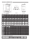
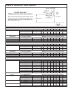
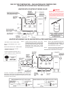
MINIMUM CLEARANCES TO COMBUSTIBLES IN INCHES (mm)
MODEL ”A” ”B” ”C” ”D”
RIGHT LEFT BACK CEILING
SIDE SIDE
SBN71120NE 2” (51mm) 2” (51mm) 2” (51mm) 12” (305mm)
SBN81154NE 2” (51mm) 2” (51mm) 2” (51mm) 12” (305)
SBN100180NE 2” (51mm) 2” (51mm) 2” (51mm) 12” (305)
SBN100199NE 2” (51mm) 2” (51mm) 2” (51mm) 12” (305)
SBN100250NE 2” (51mm) 2” (51mm) 2” (51mm) 12” (305)
SBN100275NE 2” (51mm) 2” (51mm) 2” (51mm) 12” (305)
SBN85310NE 6” (152mm) 6” (152mm) 6” (152mm) 12” (305)
SBN85366NE 3” (76mm) 3” (76mm) 3” (76mm) 12” (305)
SBN85390NE 3” (76mm) 3” (76mm) 3” (76mm) 12” (305)
TABLE 4
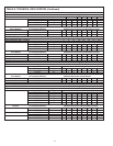
CLEARANCES TO NONCOMBUSTION CONSTRUCTION
MODEL ”A” ”B” ”C” ”D”
RIGHT LEFT BACK CEILING
SIDE SIDE
SBN71120NE 0 0 0 12” (305mm)
SBN81154NE 0 0 0 12” (305mm)
SBN100180NE 0 0 0 12” (305mm)
SBN100199NE 0 0 0 12” (305mm)
SBN100250NE 0 0 0 12” (305mm)
SBN100275NE 0 0 0 12” (305mm)
SBN85310NE 6” (152mm) 6” (152mm) 6” (152mm) 12” (305mm)
SBN85366NE 0 0 0 12” (305mm)
SBN85390NE 0 0 0 12” (305mm)
TABLE 5
ILLUSTRATION OF MINIMUM COMBUSTIBLE CLEARANCES IN AN ALCOVE - FIGURE 6