


SBD TANK TYPE HEATERS
SERVICE HANDBOOK
Technical Training Department
Ashland City, TN ©2003
35
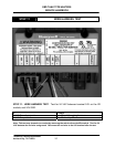
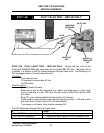
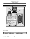
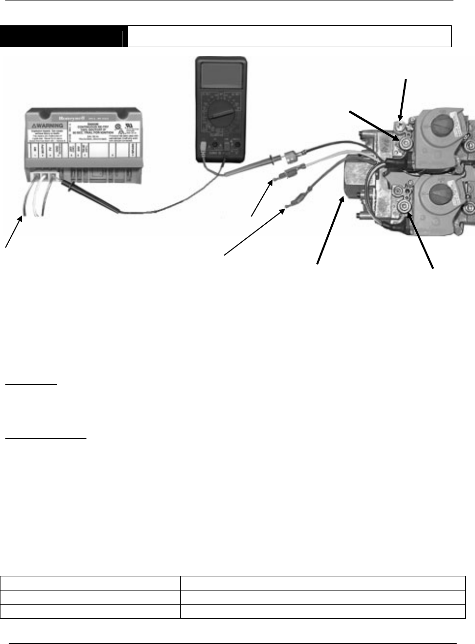
STEP 14B PILOT VALVE TEST – SBD 500 ONLY
STEP 14B. PILOT VALVE TEST – SBD 500 ONLY. Testing the two coils of the
Honeywell VR8404P 5004 gas valve used on the model SBD 500 only. Because of built
in diodes, it is difficult to test for ohms resistance through these coils. The following is a
DC amperage check of the main and pilot coils.
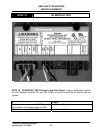
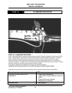
Condition:
• Tank calls for heat
• PV terminal of module has 24 Vac
• No Pilot flame
Test Procedure:
• Turn off power to heater
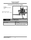
• Meter set to test for DC amperage (on meters, the black wire is in the “com”
port, the red wire is in the “10A” port, the dial is set to 20M/10A in the DC AMP
test area).
• Blue “PV” wire is disconnected from the ignition PV terminal.
• Install meter in series between gas valve and ignition module – 10A wire to blue
gas valve lead, common wire to PV module terminal.
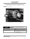
• Turn power on to heater, after module receives 24V
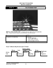
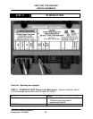
Test DC Amperage through Pilot coil of gas valve
NEHT FI
.75 to .85 DCA is not present: • Replace the gas valve
.75 to .85 DCA is present • Pilot should work if gas (not air) is present to pilot
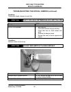
Power off, reattach blue gas valve wire to PV terminal of module.
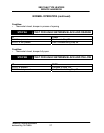
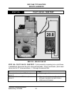
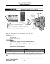
RED
WHITE
BLUE
MANIFOLD
PRESSURE
TAP
MANIFOLD
PRESSURE
TAP
PILOT GAS
MANIFOLD
GAS
The MV/PV wire on the IID is connected to the white wire
The MV wire on the IID is connected to the red wire.