


7
Continued pilot outage preceded by higher than usual water
temperature is evidence of high limit switch operation. Contact
your dealer or servicer to determine the reason for operation.
ELECTRONIC IGNITION CONTROL
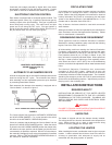
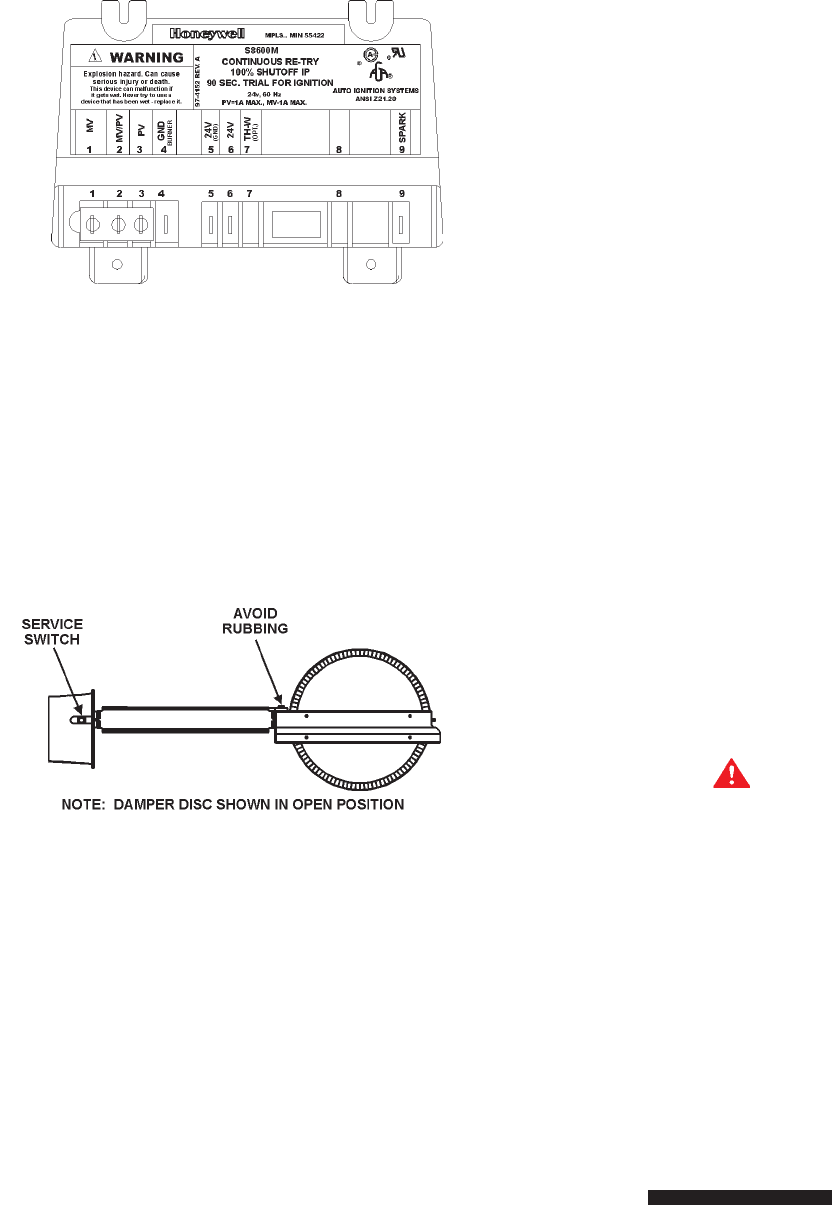
Each heater is equipped with a Honeywell ignition module. The
solid state ignition control, fig. 4, ignites the pilot burner gas by
creating a spark at the pilot assembly. Pilot gas is ignited and
burns during each running cycle. The main burner and pilot
gases are cut off during the OFF cycle. Pilot gas ignition is
proven by the pilot sensor. Main burner ignition will not occur if
the pilot sensor does not first sense pilot ignition.
HONEYWELL IGNITION MODULE
S8600M Continuous Re-Try
FIGURE 4
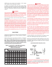
AUTOMATIC FLUE DAMPER DEVICE
All units are equipped with an automatic flue damper that reduces
heat loss during the OFF cycles. The automatic flue damper
drive assembly is a field replaceable part and may be obtained
by contacting State Water Heaters.
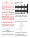
Each automatic flue damper drive assembly is equipped with a
“Service Switch”, as shown in figure 5.
FIGURE 5
The “Service Switch” has 2 positions: AUTOMATIC OPERATION
and HOLD OPEN DAMPER. For normal operation the switch
should be in the AUTOMATIC OPERATION position.
If there is a problem with the damper the “Service Switch” can be
placed in the HOLD OPEN DAMPER position. When the switch
is placed in the HOLD OPEN DAMPER position the damper disc
will rotate to the open position and the heater may be used until
vent assembly is repaired or replaced. DO NOT turn the damper
disc manually; damage will occur to the drive assembly if operated
manually. Refer to TESTING DAMPER OPERATION section of
this manual for additional information.
CIRCULATING PUMP
A circulating pump is used when a system requires a circulating
loop or there is a storage tank used in conjunction with the
heater. Refer to the piping diagrams in this manual for electrical
hookup information and install in accordance with the latest
version of the
National Electric Code ANSI/NFPA No. 70. For
Canada refer to Canadian Code CSA C22.1.
Only all bronze circulators should be used with commercial
water heaters.
Although circulators are oiled and operated by the manufacturer
some circulators must be oiled again before operating. Please
refer to manufacturer’s instructions.
DISHWASHING MACHINE REQUIREMENT
These appliances meet the National Sanitation Foundation
Standard for sanitary installations when used with the following
leg kits, Part No’s. 6570-0 and 6570-7.
All dishwashing machines meeting the National Sanitation
Foundation requirements are designed to operate with water
flow pressures between 15 and 25 psi (103 Kpa and 173 Kpa).
Flow pressures above 25 psi (173 Kpa), or below 15 psi (103
Kpa), will result in improperly sanitized dishes. Where pressures
are high, a water pressure reducing or flow regulating control
valve should be used in 180°F (82°C) line to the dishwashing
machine, and should be adjusted to deliver water between these
limits.
The National Sanitation Foundation also recommends
circulation of 180°F (82°C) water. Where this is done, the
circulation should be very gentle so that it does not cause any
unnecessary turbulence inside the water heater. The circulation
should be just enough to provide 180°F (82°C) water at the point
of take-off to the dishwashing machine. Adjust flow by means of
the plug cock in the circulating line.
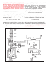
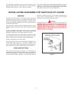
INSTALLATION INSTRUCTIONS
REQUIRED ABILITY
INSTALLATION OR SERVICE OF THIS WATER HEATER
REQUIRES ABILITY EQUIVALENT TO THAT OF A LICENSED
TRADESMAN IN THE FIELD INVOLVED. PLUMBING, AIR
SUPPLY, VENTING, GAS SUPPLY AND ELECTRICAL WORK
ARE REQUIRED.
WARNING
FAILURE TO FOLLOW THESE INSTRUCTIONS CAN RESULT
IN SERIOUS PERSONAL INJURY OR DEATH.
UNCRATING
The heater is shipped with the flue damper already installed.
The wiring conduit runs from the thermostat to the damper drive
cover. Before turning unit on, check to make sure the wiring
conduit is securely plugged into damper drive.
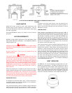
LOCATING THE HEATER
When installing the heater, consideration must be given to proper
location. Location selected should be as close to the stack or
chimney as practicable, with adequate air supply and as
centralized with the piping system as possible.