


14
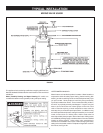
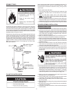
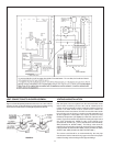
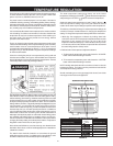
VENT CONNECTIONS TO BLOWER ASSEMBLY
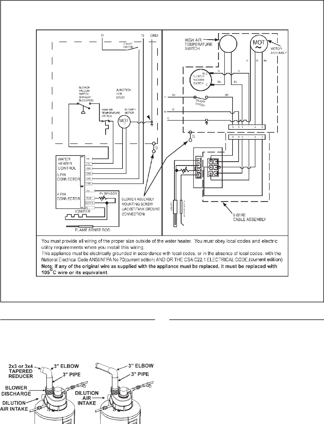
Figure 15 shows the optimal placement of the 2" to 3" or 3" to 4" reducer;
however, the vent can be reduced at any point in the vent system as long
as the maximum and minimum vent length requirements are met.
FIGURE 15.
VENTING AND INSTALLATION
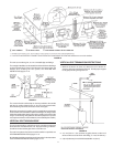
Plan the layout of the vent system from the vent termination to the
water heater considering all of the 90° and 45° elbows plus the
number of feet of pipe that would be needed to install the total vent
system. The water heater must be vented to the outdoors as
described in these instructions. DO NOT connect this water heater
to an existing vent or chimney. It must be vented separately from
all other appliances. Nonmetallic vent may be used if it has “Heat
Deflection Temperature” (HDT@66 psi) or 455 kPa of at least 157°F
or 69°C. Typical nonmetallic vent materials meeting this requirement
are: PVC (Schedule 40, ASTM D-1785), Coex Cellular Core
(Schedule 40, ASTM F-441), CPVC (Schedule 40, ASTM D-2846),
ABS (Schedule 40, ASTM D-2661). The fittings, other than the
supplied Vent Termination should be equivalent to the following:
PVC (Schedule 40, DWV, ASTM D-2665), CPVC (Schedule 40, DWV,
ASTM F-438), ABS (Schedule 40 DWV, ASTM D-2661).
The cement used should be as recommended by the vent pipe
manufacturer. See the instructions on pages 18 and 19 for the proper
method of cutting and cementing the PVC pipe and fittings.