


10
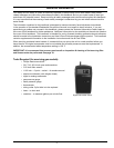
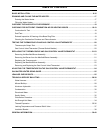
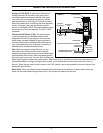
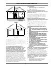
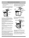
Burner/Manifold Door Assembly: The burner/manifold assembly consists of several components such as:
main burner, burner orifi ce, manifold tube, pilot burner, pilot orifi ce, pilot tube, igniter, and thermocouple. See the
fi gure below for the complete list of components.
The pilot burner remains on once it is manually lit. When incoming cold water activates the thermostat, gas fl ows
to the main burner. The pilot fl ame ignites this gas. The main fl ame burns until the tank reaches set temperature
then the thermostat interrupts this main gas fl ow.
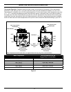
Burner Orifice*
Main Burner
Pilot (Burner)
Thermocouple
Burner Screws
Manifold Door
Door Gasket
Manifold Tube
Pilot Tube
Igniter Wire
View Port
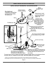
TCO (Thermal Cut
Off) Switch
Igniter Wire
TCO (Thermal Cut
Off) Sensor
Front View
TCO Reset
Button
Pilot (Burner)
Thermocouple
Pilot Orifice*
Ferrule
Pilot Nut
Pilot Tube
Pilot Bracket
*DO NOT operate the water heater without the pilot and burner orifices installed.
NOTE: The base of the
Thermocouple must be
flush with the base of
the pilot bracket.
Pilot Assembly View
Piezo Igniter Tip
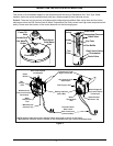
BASIC INSTALLATION & OPERATION
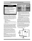
Gas Control Knob
Reset
Button
Pilot
Flame
Safety Valve
Safety Valve
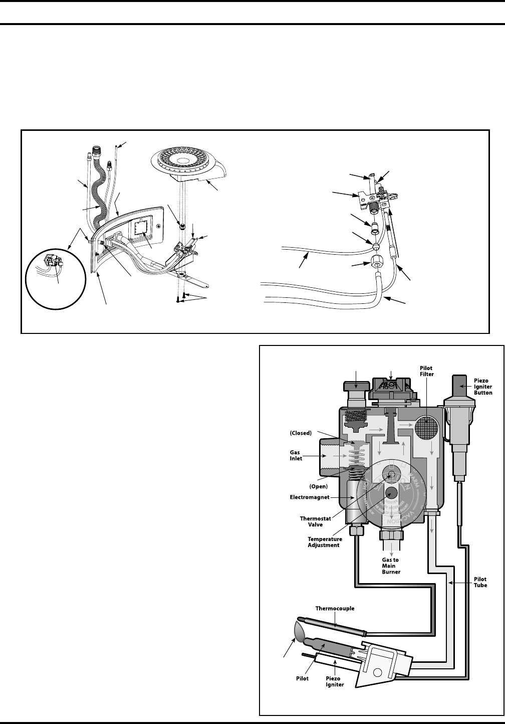
RobertShaw Gas Control Valve/Thermostat Shown.
Figure 3
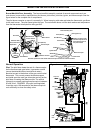
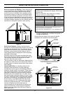
Figure 4
Normal Operation
Pilot: The pilot fl ame heats the end of a thermocouple.
As the thermocouple gets hotter, it generates a small
(cannot be detected without an electrical meter)
electrical current to the bottom of the gas control valve/
thermostat. This current powers the electromagnet
and holds open the main gas interrupter as long as the
pilot fl ame is heating the thermocouple. The normal
voltage for a properly working thermocouple is between
20 and 30 mv. DANGER! If the pilot is extinguished,
it can take up to 180 seconds for the thermocouple to
cool suffi ciently to close the safety valve.