


29
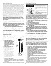
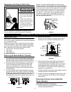
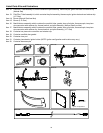
Replacing the Gas Valve:
1. To replace the gas control valve/thermostat,
reassemble in reverse order. When replacing the gas
control valve/ thermostat, thread a correctly sized
pipe into the inlet and use it to turn the gas valve
(clockwise.) DO NOT OVER TIGHTEN or damage may
result. NOTE: Use an approved
TEFLON
®
tape or pipe
compound only on the threaded section of the gas
control valve/thermostat that screws into the tank.
2. Reconnect the gas piping to the gas control valve/
thermostat. NOTE: Use an approved Teflon tape or
pipe compound on the gas piping connections.
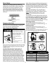
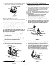
3. Attach the igniter and bracket to the new gas control
valve/thermostat, clipping it at the back edge of
thermostat and snapping it into place. NOTE: Do not
use the (pilot) ferrule nut supplied with the new gas
control valve/thermostat, unless the existing nut is not
usable. Reconnect the pilot tube, manifold tube, igniter
wire, and thermal switch wires. NOTE: L.P. gas systems
use reverse (left-hand) threads on the manifold tube.
4. Fill the tank completely with water. NOTE: To purge the
lines of any excess air, keep the hot water faucet open
for 3 minutes after a constant flow of water is obtained.
5. Turn on the gas supply and test the gas supply
connections by brushing on an approved noncorrosive
leak detection solution. Bubbles forming indicate a
leak. Correct any leak found.
6. Check the operation of the burner by following the
lighting instructions on the front of the water heater.
With the burner lit, check the gas control valve/
thermostat supply line, manifold tube and pilot tube
connections for leaks.
7. Verify proper operation and then replace the outer door.
8. If additional information is required, contact Residential
Technical Assistance by referencing the phone number on
the water heater.
TEFLON
®
is a registered trademark of E.I. Du Pont De Nemours and Company
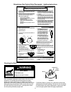
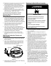
FVIR System Operational Checklist
1. Manifold gasket properly sealed.
2. Viewport not damaged or cracked.
3. Flame-arrestor free of debris and undamaged.
4. Two piece wire connector properly installed.
5. No leaks at pilot and manifold connection.
6. Manifold door screws securely tightened.
7. Depress the button on the thermal switch
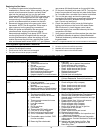
TROUBLESHOOTING CHART
PROBLEM POSSIBLE CAUSE(S) CORRECTIVE ACTION
BURNER WILL NOT IGNITE
1. Pilot not lit
2. Thermostat set too low
3. No gas
4. Dirt in the gas lines
5. Pilot line clogged
6. Main burner line clogged
7. Non-functioning thermocouple
8. Non-functioning thermostat
9. Heater installed in a confined area
1. Light pilot
2. Turn temp. dial to desired temperature
3. Check with gas utility company
4. Notify utility-install trap in gas line
5. Clean, locate source and correct
6. Clean, locate source and correct
7. Replace thermocouple
8. Replace thermostat
9. Provide fresh air ventilation
SMELLY WATER
1. Sulfides in the water 1. Replace the anode with a special anode.
Contact Residential Technical Assistance
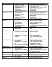
BURNER FLAME YELLOW-
LAZY
1. Insufficient secondary air
2. Low gas pressure
3. Water heater flue or vent system
blocked
4. Main burner line clogged
5. Heater installed in a confined area
6. Obstruction in main burner orifice
1. Provide ventilation to water heater
2. Check with gas utility company
3. Clean, locate source and correct
4. Clean, locate source and correct
5. Proper fresh air ventilation
6. Clean or replace orifice
PILOT WILL NOT LIGHT OR
REMAIN LIT
1. Non-functioning igniter
2. The thermal switch tripped
3. Wire lead connection at thermal
switch loose
4. Thermocouple connection loose
5. Air in gas line
6. Low gas pressure
7. No gas
8. Dirt in gas lines
9. Cold drafts
10. Thermostat ECO switch open
11. Pilot line or orifice clogged
12. Non-functioning thermocouple
13. Air for combustion obstructed
14. Flammable vapors incident, FVIR
function actuated
15. Base-ring filter obstructed
1. Replace igniter pilot assembly
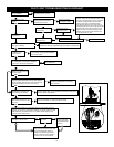
2. See Pilot Light Troubleshooting Flowchart section
3. Remove and reconnect the wire leads at
thermal switch, confirm connections are tight
and not loose
4. Finger tighten; then 1/4 turn with wrench
5. Bleed the air from the gas line
6. Check with gas utility company
7. Check with gas utility company
8. Notify utility-install dirt trap in gas line
9. Locate source and correct
10. Replace thermostat
11. Clean, locate source and correct
12. Replace thermocouple
13. See maintenance section for inspection and
cleaning of flame trap
14. Replace water heater, eliminate flammable
vapors source. Contact Residential Technical
Assistance
15. Inspect and clean base-ring filter. See
“External Cleaning & Inspection of the
Base-Ring Filter.”