


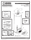
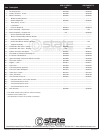

GS6 50 YRVIT 5 GS6 50 HRVIT 5
Item Description 100 101
1 ......Air Intake Screen ........................................................................................................... 9003406 ..........................................9003406
2 ......Anode, Aluminum - 6 Year ............................................................................................. 9000029 ..........................................9000029
3 ......Blower Assembly .......................................................................................................... 9006030 ..........................................9006030
4 ...... Blower Assembly Gasket ........................................................................................... ------------ ..........................................------------
5 ...... Exhaust Adaptor Kit .................................................................................................... 9006020 ..........................................9006020
6 ...... Hose Clamp - 4 inch***.............................................................................................. ------------ .......................................... ------------
7 ...... Limit Switch** ............................................................................................................. ------------ ..........................................------------
8 ...... Pressure Switch Kit .................................................................................................... 9006019 ..........................................9006019
9 ......Burner Assembly - Natural Gas .................................................................................... 9006024 .............................................. N/A
9 ......Burner Assembly - Propane Gas .......................................................................................N/A ...............................................9006026
10 ...... Burner Head with Door Gasket .................................................................................. ------------ ..........................................------------
11 ...... Burner Tube Assembly with Door Gasket.................................................................. ------------ ..........................................------------
12 ...... Inner Door with Door Gasket ..................................................................................... ------------ ..........................................------------
13 ...... Orifice, Main Burner with Door Gasket ....................................................................... ------------ .............................................. N/A
14 ...... Viewport Assembly ..................................................................................................... ------------ ..........................................------------
15 ......Combination Gas Valve - Natural ................................................................................. 9004267 .............................................. N/A
15 ......Combination Gas Valve - Propane ....................................................................................N/A ...............................................9004464
16 ......Diffuser Inlet Tube with Spacer ..................................................................................... 9006021 ..........................................9006021
17 ......Flue Baffle and Restrictor Assembly Kit ....................................................................... 9006028 ..........................................9006028
18 ......FV Sensor and Bracket Kit ............................................................................................ 9006029 ..........................................9006029
19 ......Igniter Assembly, Hot Surface With Door Gasket ......................................................... 9005958 ..........................................9005958
20 ......Inner Door Gasket ......................................................................................................... 9003398 ..........................................9003398
21 ......Nipples - 5 inch ............................................................................................................. 9003977 ..........................................9003977
22 ......Outer Door..................................................................................................................... 9003545 ..........................................9003545
23 ......Thermostat Shield (optional) ........................................................................................ 9005693 ..........................................9005693
24 ......Turbo Inlet Tube with Spacer ........................................................................................ 9004016 ..........................................9004016
25 ......Valve, Drain - Brass....................................................................................................... 9001870 ..........................................9001870
26 ......Valve, T&P Relief ...........................................................................................................
9000728 ..........................................9000728
27 ......Vent Terminal Screen Kit ............................................................................................... 9006027 ..........................................9006027
28 ...... Instruction Sheet - 2, 3 & 4 inch Screens................................................................... ------------ ..........................................------------
29 ...... Vent Terminal Screen 2 inch ...................................................................................... ------------ ..........................................------------
30 ...... Vent Terminal Screen 3 inch ...................................................................................... ------------ ..........................................------------
31 ...... Vent Terminal Screen 4 inch ...................................................................................... ------------ ..........................................------------
32 ......Wire Harness ................................................................................................................ 9006022 ..........................................9006022
** Limit Switch located inside control box of blower assembly.
*** Available at local hardware store.
Parts listed without numbers are available as assemblies.
2 of 2
State Water Heater Parts Fulfillment • 125 Southeast Parkway • Franklin, TN 37068 • 1-800-821-2017 • www.statewaterheaters.com
PRINTED IN THE U.S.A. 0606 185476-001