


13
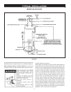
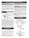
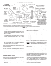
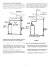
Figure 10 shows typical attachment of water piping to water heater. The
water heater is equipped with 3/4 inch NPT water connections.
NOTE: If using copper tubing, solder tubing to an adapter before
attaching the adapter to the water heater connections. Do not
solder the water lines directly to the water heater connections.
It will harm the dip tube and damage the tank.
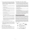
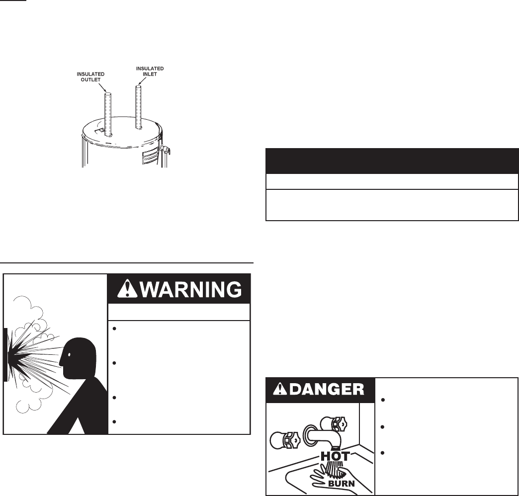
T & P Valve and Pipe Insulation (if supplied)
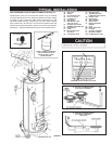
Remove insulation for T & P valve and pipe connections from carton.
FIGURE 11.
Fit pipe insulation over the incoming cold water line and the hot water
line. Make sure that the insulation is against the top cover of the heater.
Fit T & P valve insulation over valve. Make sure that the insulation
does not interfere with the lever of the T & P valve.
Secure all insulation using tape.
TEMPERATURE-PRESSURE RELIEF VALVE
Explosion Hazard
Temperature-Pressure Relief Valve
must comply with ANSI Z21.22-
CSA 4.4 and ASME code.
Properly sized temperature-
pressure relief valve must be
installed in opening provided.
Can result in overheating and
excessive tank pressure.
Can cause serious injury or death.
This water heater is provided with a properly rated/sized and certied
combination Temperature-Pressure Relief Valve (T&P valve) by
the manufacturer. The valve is certied by a nationally recognized
testing laboratory that maintains periodic inspection of production of
listed equipment of materials as meeting the requirements for Relief
Valves for Hot Water Supply Systems, ANSI Z21.22 • CSA 4.4, and
the code requirements of ASME.
If replaced, the new T&P valve must meet the requirements of local
codes, but not less than a combination Temperature-Pressure Relief
Valve rated/sized and certied as indicated in the above paragraph. The
new valve must be marked with a maximum set pressure not to exceed
the marked hydrostatic working pressure of the water heater (150 psi =
1,035 kPa) and a discharge capacity not less than the water heater Btu/
hr or kW input rate as shown on the water heater’s model rating label.
NOTE: In addition to the factory installed Temperature-Pressure
Relief Valve on the water heater, each remote storage tank that may
be installed and piped to a water heating appliance must also have its
own properly sized, rated and approved Temperature-Pressure Relief
Valve installed. Call the toll free technical support phone number
listed on the back cover of this manual for technical assistance in
sizing a Temperature-Pressure Relief Valve for remote storage tanks.
For safe operation of the water heater, the Temperature-Pressure
Relief Valve must not be removed from its designated opening nor
plugged. The Temperature-Pressure Relief Valve must be installed
directly into the tting of the water heater designed for the relief valve.
Install discharge piping so that any discharge will exit the pipe within
6 inches (15.2 cm) above an adequate oor drain, or external to the
building. In cold climates it is recommended that it be terminated at
an adequate drain inside the building. Be certain that no contact is
made with any live electrical part. The discharge opening must not
be blocked or reduced in size under any circumstances. Excessive
length, over 30 feet (9.14 m), or use of more than four elbows can
cause restriction and reduce the discharge capacity of the valve.
No valve or other obstruction is to be placed between the Temperature-
Pressure Relief Valve and the tank. Do not connect discharge piping
directly to the drain unless a 6” (15.2 cm) air gap is provided. To prevent
bodily injury, hazard to life, or property damage, the relief valve must be
allowed to discharge water in adequate quantities should circumstances
demand. If the discharge pipe is not connected to a drain or other
suitable means, the water ow may cause property damage.
Water Damage Hazard
Temperature-Pressure Relief Valve discharge
pipe must terminate at adequate drain.
•
CAUTION
T&P Valve Discharge Pipe Requirements:
• Shall not be smaller in size than the outlet pipe size of the valve,
or have any reducing couplings or other restrictions.
• Shall not be plugged or blocked.
• Shall not be exposed to freezing temperatures.
• Shall be of material listed for hot water distribution.
• Shall be installed so as to allow complete drainage of both the
Temperature-Pressure Relief Valve and the discharge pipe.
• Must terminate a maximum of six inches above a oor drain or
external to the building. In cold climates, it is recommended that
the discharge pipe be terminated at an adequate drain inside
the building.
• Shall not have any valve or other obstruction between the relief
valve and the drain.
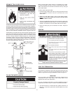
Burn hazard.
Hot water discharge.
Keep clear of Temperature-
Pressure Relief Valve
discharge outlet.
The Temperature-Pressure Relief Valve must be manually operated
at least twice a year. Caution should be taken to ensure that (1) no
one is in front of or around the outlet of the Temperature-Pressure
Relief Valve discharge line, and (2) the water manually discharged
will not cause any bodily injury or property damage because the
water may be extremely hot. If after manually operating the valve, it
fails to completely reset and continues to release water, immediately
close the cold water inlet to the water heater, follow the draining
instructions in this manual, and replace the Temperature-Pressure
Relief Valve with a properly rated/sized new one.
NOTE: The purpose of a Temperature-Pressure Relief Valve is to
prevent excessive temperatures and pressures in the storage tank.
The T&P valve is not intended for the constant relief of thermal
expansion. A properly sized thermal expansion tank must be installed
on all closed systems to control thermal expansion, see Closed
Water Systems and Thermal Expansion on page 12.
If you do not understand these instructions or have any questions
regarding the Temperature-Pressure Relief Valve call the toll free
number listed on the back cover of this manual for technical assistance.