


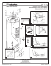
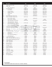


1 .......... Anode, Aluminum Alloy ..........................................183523-26 ....................... 183523-26.......................... 183523-29 ........................
2 .......... Baffle, Flue ............................................................ 185111-000 ......................185111-000........................ 184974-000 .......................
3 ................. Ring, Flue Restrictor ..........................................34894-1 ........................... 34894-1.............................. 34894-1 ..........................
4 .......... Blower Assembly...................................................184955-000 ......................184955-000........................ 184955-000 .......................
**5 ............... Limit Switch .................................................... 183380-004 ......................183380-004........................ 183380-004 .......................
6 ................. Pressure Switch ..............................................185110-000 ......................185110-000........................ 185110-000 .......................
7 ................. Adapter, Exhaust ............................................185215-000 ......................185215-000........................ 185215-000 .......................
8 ................. Hose Clamp .................................................... 183545-001 ......................183545-001........................ 183545-001 .......................
9 ................. Gasket ............................................................ 184956-000 ......................184956-000........................ 184956-000 .......................
10 ......... Burner Assembly, Natural Gas .................................. - - - - -...........................185126-004............................ - - - - - ...........................
10 ......... Burner Assembly, Propane Gas ............................ 185127-004 .......................... - - - - - ............................ 185127-005 .......................
11 ................ Burner, Main - Natural ......................................... - - - - -...........................183504-000............................ - - - - - ...........................
11 ................ Burner, Main - Propane ...................................... 183325 .............................. - - - - - ............................... 183325 ...........................
12 ................ Igniter Assembly, Hot Surface.........................185148-000 ......................185148-000 ........................ 185148-000 .......................
13 ................ Orifice, Main Burner - Natural .............................. - - - - -...........................
181508-31............................. - - - - - ...........................
13 ................ Orifice, Main Burner - Propane ........................181791-048 .......................... - - - - - ............................. 181791-48 .......................
.
14 ................ Burner Tube Assembly - Natural ......................... - - - - -.............................184051-2 .............................. - - - - - ...........................
14 ................ Burner Tube Assembly - Propane .....................184049-2 ............................- - - - -.............................. 184049-3 ........................
.
15 ......... Combination Gas Valve - Natural ............................... - - - - -...........................184768-002............................ - - - - - ...........................
15 ......... Combination Gas Valve - Propane ......................... 184768-003 .......................... - - - - - ............................ 184768-003 .......................
16 ......... Door, Inner ................................................................ 183491 ............................. 183491 .............................. 183491 ...........................
17 ......... Door, Outer ............................................................... 180522 ............................. 180522 .............................. 180522 ...........................
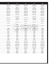
18 ......... Envelope with Parts ............................................... 183509-003 ......................183509-003........................ 183509-003 .......................
19 ................ Wall Plate, 2" ..................................................... 182787 ............................. 182787 .............................. 182787 ...........................
20 ................ Wall Plate, 3" ..................................................... 181557 ............................. 181557 .............................. 181557 ...........................
21 ................ Vent Terminal Assembly, 2" ...........................183006-000 ......................183006-000........................ 183006-000 .......................
22 ................ Vent Terminal, 3" ............................................... 192815 ............................. 192815 .............................. 192815 ...........................
*23 ........ Label, Electrical Diagram ......................................... 183765 ............................. 183765 .............................. 183765 ...........................
24 ......... Label, Flammable Vapor/Scald Warning ................... 183301 ............................. 183301 .............................. 183301 ...........................
25 ......... Label, Lighting & Operating Instruction ..................... 183764 ............................. 183764 .............................. 183764 ...........................
*26 ........ Label, Relief Valve .................................................... 180078 ............................. 180078
.............................. 180078 ...........................
*27 ........ Label, Temperature ................................................... 182734 ............................. 182734 .............................. 182734 ...........................
*28 ........ Owner’s Manual ..................................................... 185171-000 ......................185171-000........................ 185171-000 .......................
29 ......... Pipe Insulation, 2' ..................................................181639-003 ......................181639-003........................ 181639-003 .......................
30 ......... Insulation, T & P ....................................................183256-000 ......................183256-000........................ 183256-000 .......................
31 ......... Heat Trap Nipples .................................................. 184715-003 ......................184715-003........................ 184715-003 .......................
32 ......... Spacer, Inlet Tube ................................................. 184011-000 ......................184011-000........................ 184011-000 .......................
33 ......... Tube, Inlet..............................................................184223-041 ......................184223-041 ........................ 184223-045 .......................
34 ......... Valve, Drain - Brass..................................................26273-6 ........................... 26273-6.............................. 26273-6 ..........................
35 ......... Valve, Drain - Plastic ................................................42037-3 ........................... 42037-3.............................. 42037-3 ..........................
36 ......... Valve, T & P Relief ....................................................43151-2 ........................... 43151-2.............................. 43151-2 ..........................
37 ......... Wire Harness ..........................................................183506-1 ..........................183506-1 ............................ 183506-1 .........................
38 ......... Dirt Leg Assembly ................................................... 181206-1 ..........................181206-1 ............................ 181206-1 .........................
PR6 40 CCVIT 2 PR6 40 XCVIT 2 PR6 50 CCVIT 2
Item Description 201 200 201
* Not illustrated.
** Limit Switch located inside control box of blower assembly.