


9
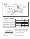
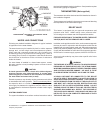
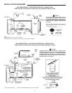
DIRECT VENTING - FOR GPV MODELS
All exhaust vent terminal, ue reducer, and intake vent terminal
are supplied with any unit intended for direct venting. These parts
must be installed without alteration.
This heater is category III appliance when used in a direct
vent application. All national and local codes pertaining to the
installation of such an appliance must be followed.
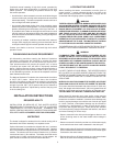
Horizontal portions of the exhaust vent system must be installed
with a minimum upward slope of 1/4” (6.35 mm) per foot of
length.
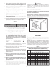
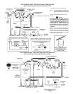
Selkirk metalbestos model PS or G vent is approved for use as
exhaust venting on these models. Model PS is a double-wall
vent with a 1” (25.4 mm) air space between pipes. Model G is
a single-wall variation of model PS for use where combustible
clearance is not a concern, see Table 4.
TABLE 4.
Selkirk Metalbestos Model PS
Clearance to Combustibles
Interior 6” (152.4 mm)
Exterior 6” (152.4 mm)
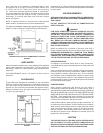
8” diameter PVC or galvanized pipe is approved for use as
intake venting on these models. Class 63, 100, 125, 200, and
schedule 40 pipe may be used for PVC pipe. Intake venting
must be adequately supported to avoid unnecessary stress on
vent hood, venting, or burner.
See Table 5 limitations on venting system design for direct vent
installations.
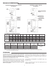
TABLE 5.
Dimension in GPV
Inches
(mm) 540A -740A
Flue Outlet Dia. 9 (229)
Flue Reducer Dimension 9 x 8
(Supplied) (229 x 203)
Min. Exhaust Vent Dia. Inch (mm) 8 (203)
Min. Intake Vent Dia. Inch (mm) 8 (203)
Maximum Number Of 90° 4
Elbows, Intake 45° 8
Maximum Number Of 90° 4
Elbows, Exhaust 45° 8
Total Intake Vent Max. 75 (23 m)
Length, Equiv. Ft. Min. 3 (1 m)
Total Exhaust Vent Max. 75 (23 m)
Length, Equiv. Ft. Min. 6 (1.8)
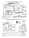
Note: Barometric draft control is not used in direct vent installations
as the venting system must be sealed.
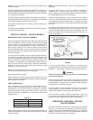
When calculating the equivalent length of a venting system each
90 elbow is equivalent to 10 feet of straight pipe. Each 45 elbow
is equivalent to 5 feet (1.5 m) of straight pipe. Do not exceed the
maximum number of elbows as shown in Table 5. In no case may
the sum of the straight pipe lengths and the equivalent lengths of
the elbows exceed the valves in Table 5.
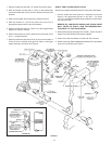
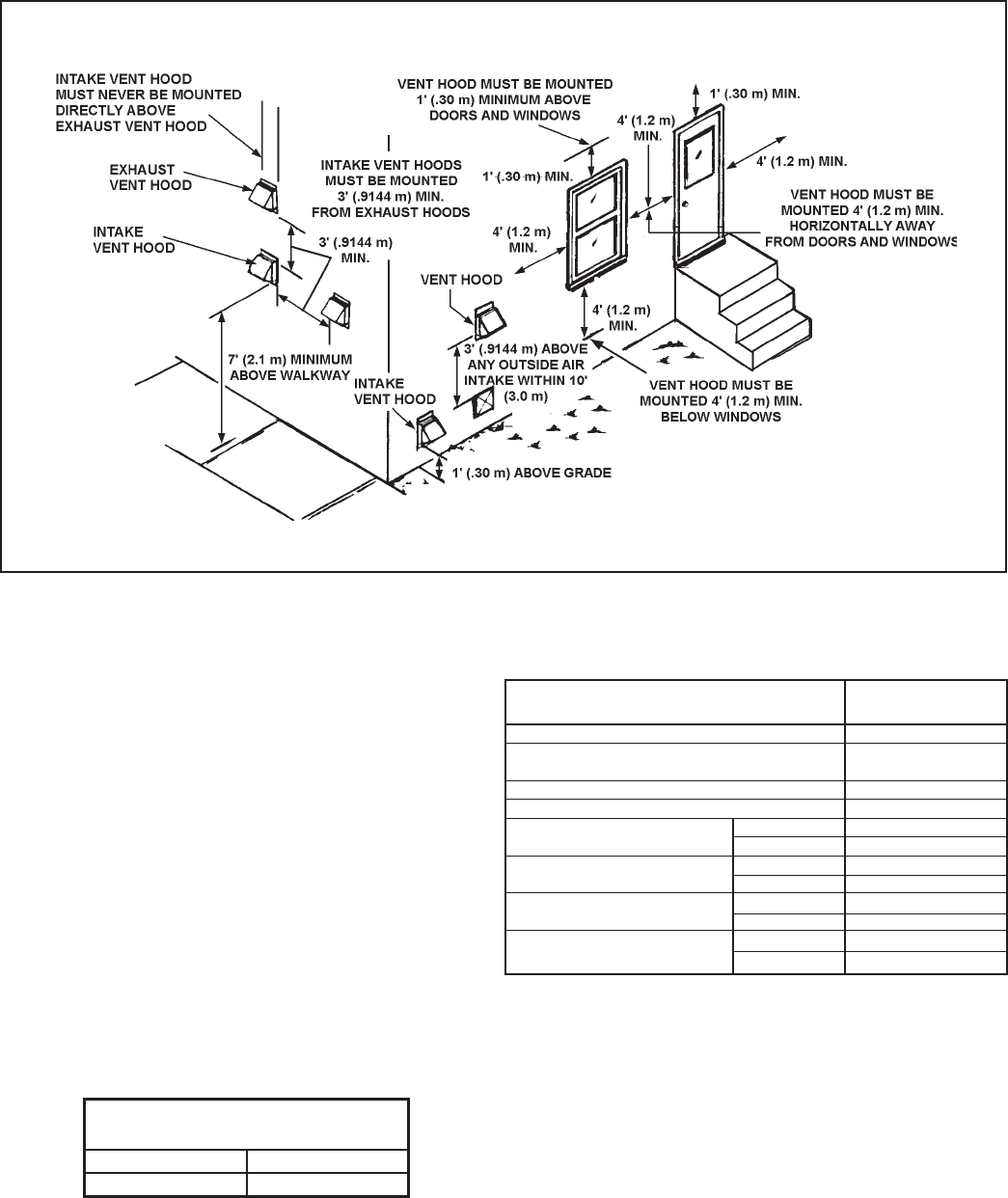
VENT TERMINAL LOCATIONS-EXHAUST
See “Horizontal Venting” in this manual for acceptable locations
for exhaust hoods.
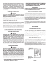
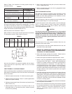
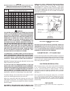
VENT TERMINAL LOCATIONS-INTAKE
When considering locations for the intake terminal, bear in mind
that the terminal:
FIGURE 6.