


14
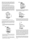
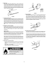
SEDIMENT TRAPS
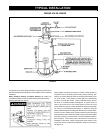
A sediment trap shall be installed as close to the inlet of the water
heater as practical at the time of water heater installation. The sediment
trap shall be either a tee fi tting with a capped nipple in the bottom
outlet or other device recognized as an effective sediment trap. If a
tee fi tting is used, it shall be installed in conformance with one of the
methods of installation shown in Figures 12 and 13.
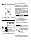
Contaminants in the gas lines may cause improper operation of the
gas control valve that may result in fi re or explosion. Before attaching
the gas line be sure that all gas pipe is clean on the inside. To trap any
dirt or foreign material in the gas supply line, a drip leg (sometimes
called a sediment trap) must be incorporated in the piping. The drip leg
must be readily accessible. Install in accordance with the “Gas Piping”
section. Refer to the current edition of the National Fuel Gas Code,
ANSI Z223.1/NFPA 54.
FIGURE 14.
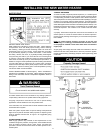
FILLING THE WATER HEATER
Never use this water heater unless it is completely full of water. To prevent
damage to the tank, the tank must be fi lled with water. Water must fl ow
from the hot water faucet before turning “ON” gas to the water heater.
To fi ll the water heater with water:
1. Close the water heater drain valve by turning the handle to the
right (clockwise). The drain valve is on the lower front of the water
heater.
2. Open the cold water supply valve to the water heater.
NOTE: The cold water supply valve must be left open when
the water heater is in use.
3. To insure complete fi lling of the tank, allow air to exit by opening
the nearest hot water faucet. Allow water to run until a constant
fl ow is obtained. This will let air out of the water heater and the
piping.
4. Check all water piping and connections for leaks. Repair as
needed.
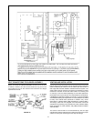
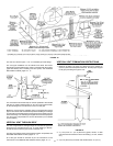
BLOWER ASSEMBLY INSTALLATION
SEQUENCE OF INSTALLATION
1. This power vented water heater comes with the blower assembly
installed.
2 After the unit is set in place, make sure the blower assembly is still
mounted securely and the air intake screen of the blower assembly
is installed in the dilution air opening. Also make sure the drain
port of the rubber boot vent adapter is capped off. Lastly, make
sure there is no damage to the blower.
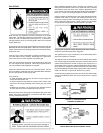
3. Make sure there is no packing material in the discharge of the
blower or the intake of the dilution air restrictor, see Figure 15.
4. Make sure that the plastic tubing is still attached from the air pressure
switch to the port on the blower housing. Make sure the plastic tubing
is not folded anywhere between the pressure switch and the blower
housing.
5. Make sure the ON/OFF switch is in the OFF position and that the
outer harness is connected from the blower control box to the
connector on the bottom side of the gas control valve.
6. If the outer harness is not factory installed, make sure the ON/OFF
switch is in the OFF position and then connect the outer harness
from the blower control box to the connector on the bottom side
of the gas control valve.
7. This water heater is a polarity sensitive appliance and will not operate if
the power supply polarity is reversed. The power supply or outlet providing
power to this water heater must be wired properly (correct polarity).
8. Do not plug in power cord until vent system is completely installed. This
powered vent heater operates on 110-120 Vac, therefore a grounded
outlet must be within reach of the six (6) foot (1.8 m) fl exible power
cord supplied with the unit (see Figure 1). The power cord supplied
may be used only where local codes permit. If local codes do not
permit the use of a fl exible power supply cord:
a.) Make sure the unit is unplugged from wall outlet. Remove screws
and open panel on front of control box.
b.) Cut the fl exible power cord, leaving enough to be able to make
connections, the remove the strain relief fi tting from box.
c.) Install suitable conduit fi tting in side of enclosure and then follow
(d.) and (e.) below.
d.) Splice fi eld wiring into existing wiring using code authorized method
(wire nuts, etc.).
e.) Be certain that neutral and live connections are not reversed when
making these connections.
f.) Close panel on the side of control box, make sure that access
panel is secured shut.