


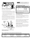
HEATER CLEARANCES –
OUTDOOR SHELTER (Canada) or INDOOR (U.S.)
The following clearances must be maintained from com-
bustible surfaces:
TOP ...........................6 INCHES (15cm)
ALL SIDES..................6 INCHES (15cm)
VENT .........................6 INCHES (15cm)
The heater is design certified by CSA International for
installation on combustible flooring. For installation on car-
peting, the heater must be mounted on a metal or wood
panel that extends at least three inches (10cm) beyond the
base of the heater. If the heater is installed in a closet or
alcove, the entire floor shall be covered by the panel.
On an outdoor shelter installation, the exhaust discharges
into a vent pipe. Orient the heater so that the vent pipe does
not interfere with adjustment of the operating controls. The
operating control panel located on top of the jacket can be
rotated for convenient access to the control panel.
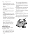
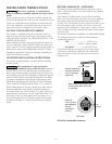
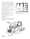
COMBUSTION AND VENTILATION AIR SUPPLY
For shelter installation, the heater requires air supply open-
ings for ventilation and combustion. The minimum require-
ments are for two (2) openings: one 12 inches (30cm) from
the ceiling for ventilation air and one 12 inches (30cm) from
the floor for combustion air, in accordance with the latest
edition of ANSI Z223.1, or the National Fuel Gas code, the
CSA B149.1, Natural Gas and Propane Installation Codes, as
applicable, and any local codes that may apply.
The minimum net free area in square inches shall be
as follows:
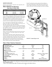
OUTDOOR SHELTER VENT
INSTALLATION (Canada) or
INDOOR INSTALLATION (U.S.)
Always vent the heater to the outdoors.
•Vent it horizontally or vertically using a Special Gas
Vent, (see Table 4, Page 14), or
•Vent it vertically using Type “B” double wall vent con-
nector pipe.
Locate the heater so as to minimize the length of horizon-
tal venting and the number of vent elbows required.
Horizontal vent runs must slope up 1/4” per foot (2cm/M)
from the heater to allow exhaust condensate to drain and
must have a condensate drain as described in the venting
installation instructions.
11
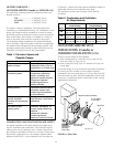
Area Likely Contaminants
Chlorinated swimming Pool or spa cleaning
pools and spas chemicals. Acids, such as
hydrochloric or muriatic acid
New construction and Glues and cements,
remodeling areas construction adhesives,
paints, varnishes, and
paint and varnish strippers.
Waxes and cleaners
containing calcium or
sodium chloride
Beauty parlors Permanent wave solutions,
bleaches, aerosol cans
containing chlorocarbons
or fluorocarbons
Refrigeration plants or Refrigerants, acids, glues
various industrial and cements, construction
finishing and processing adhesives
plants
Dry cleaning and Bleaches, detergents, or
laundry areas laundry soaps containing
chlorine.
Waxes and cleaners
containing chlorine,
calcium or sodium chloride
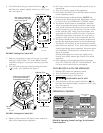
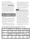
All Air From All Air From
Inside Building Outside Building
Model Combustion Vent Combustion Vent
200
200 sq. in. 200 sq. in. 50 sq. in. 50 sq. in.
1,291 sq. cm. 1,291 sq. cm. 323 sq. cm. 323 sq. cm.
333
333 sq. in. 333 sq. in. 84 sq. in. 84 sq. in.
2,149 sq. cm. 2,149 sq. cm. 542 sq. cm. 542 sq. cm.
400
400 sq. in. 400 sq. in. 100 sq. in. 100 sq. in.
2,581 sq. cm. 2,581 sq. cm. 645 sq. cm. 645 sq. cm.
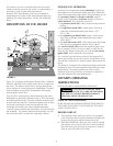
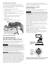
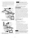
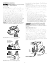
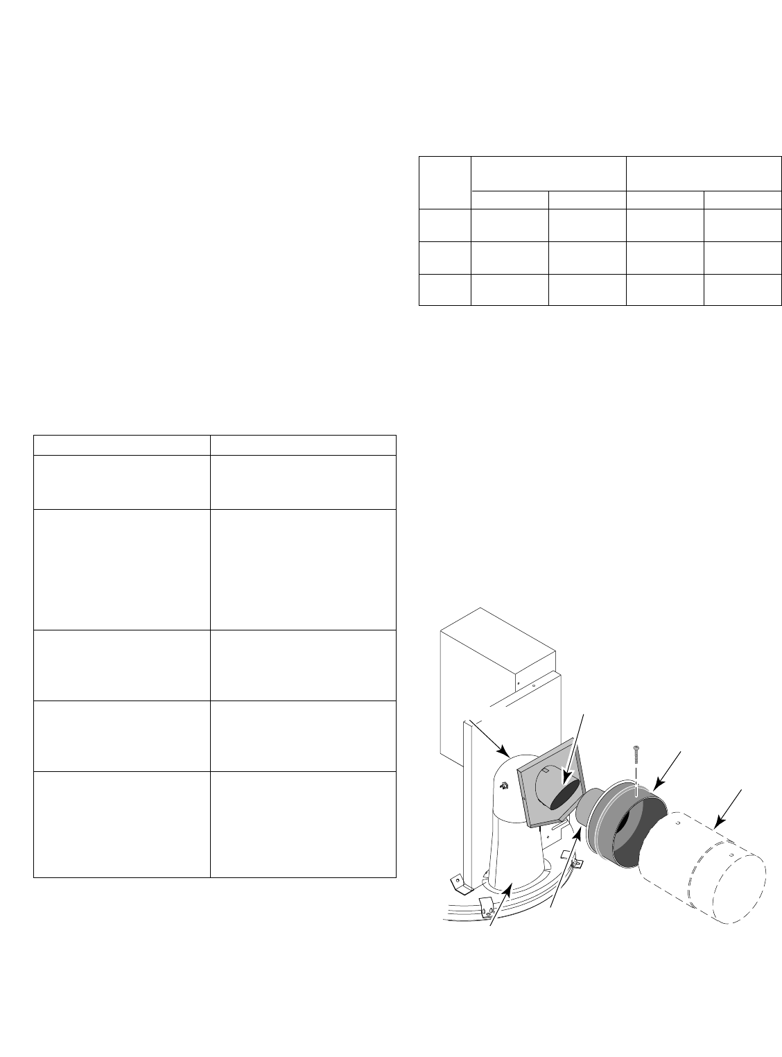
Combustion
Chamber
Flue Collar
4" x 8" Metal
Flue Collar
Vent Body
2855 0597 RTV
Clean the Interior Surface
Vent Pipe
Clean and RTV
This Surface
Table 1: Corrosive Vapors and
Possible Causes
FIGURE 11: Flue Collar
Table 2: Combustion and Ventilation
Air Requirements