


3
Assembly
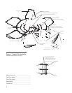
1. Visually inspect all tapped blade mounting holes for any debris which
could cause problems when tightening cap screws.
2. Install blades with rotation arrow on top side and pointing in a clockwise
direction.
3. Hold each blade level and tighten the six cap screws just enough to hold
the blade level.
4. Do not torque cap screws. Blades must be free to turn in retaining ring
to adjust pitch.
The trial pitch angle is the calculated setting for design conditions
(water rate, heat load, air density, and brake horsepower). The trial
blade pitch is provided on page 2.
Blade Pitching
5. Select a position on the fan circumference and rotate each blade to this
common location when setting or checking blade pitch. All blades must
be pitched with the blade axis pointing in the same direction. Support
the blade tip to maintain the proper plane of rotation while setting the
fan pitch.
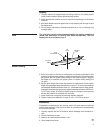
6. Set the pitch angle and torque cap screws for each blade. Set the pitch
angle using a straight edge and bevel protractor 2" (51mm) from blade tip
as illustrated. Blades should be within ±
1
⁄4° of the desired pitch. After the de-
sired pitch is obtained progressively tighten blade cap screws to 30-35 ft·lb
ƒ
(41-47 N·m) torque. A crowfoot wrench may be necessary to torque cap
screws that cannot be reached with a socket.
7. Install hub cover using cap screws and resilient washers.
8. Tighten cap screws between 10 and 15 ft·lb
ƒ
(14-20 N·m) torque.
Maintenance
Preventative maintenance will prolong useful life and assure continued
trouble-free operation. After the rst week of operation and subsequently
at six month intervals:
1. Visually inspect the fan for airborne debris damage and corrosive at-
tack.
2. Torque blade cap screws.
3. Remove any accumulated scale or dirt.
4. Clear blade drain holes.
➠
PITCH ANGLE
± 1/4°
AIR
FLOW
ROTATION
BEVEL
PROTRACTOR
STRAIGHT
EDGE
Note